
Flashing Light Circuit with Transistors

The circuit consists of a power supply, typically a battery or a DC adapter providing 6 volts, which feeds into a control mechanism that regulates the flashing of the light bulb. The primary components of this circuit include a timer IC, such as the 555 timer, configured in astable mode to generate a square wave output. This output is used to drive a transistor, which acts as a switch to control the light bulb.
When the circuit is powered, the 555 timer oscillates between its high and low states, causing the transistor to turn on and off rapidly. This switching action results in the light bulb flashing at a specific frequency, which can be adjusted by changing the resistor and capacitor values connected to the timer IC. The low current consumption when the light bulb is off is achieved by ensuring that the circuit enters a low-power state during the off phase, which minimizes power usage.
Additional components may include a diode for reverse polarity protection, ensuring that the circuit is not damaged if the power supply is connected incorrectly. A capacitor can also be placed across the power supply to filter out any noise, providing a stable voltage to the circuit. The entire assembly can be mounted on a PCB for ease of use and reliability, allowing for various applications such as decorative lighting, indicators, or signaling devices.This simple flashing light circuit is powered with 6 volts/0.5A and has a low current consumption when the light bulb is off. The flashing frequency is set.. 🔗 External reference
Related Circuits
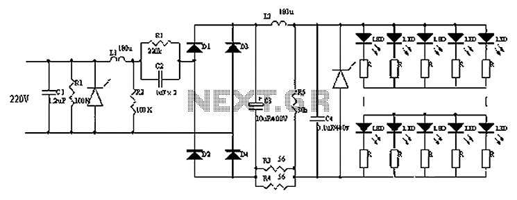
Circuits C1, R1, varistors, L1, and R2 form a filter circuit that includes a primary power supply capable of filtering out transient overvoltage inputs. The circuit also consists of C2 and R2, with additional components C3, C4, and L2....

The BE-150 mainframe computer features a switching power supply circuit. The circuit utilizes the oscillation control IC TIA94. A 22V voltage is supplied through the power switch S1, fuse, filter capacitor C21, L2, and a mutual inductance filter, which...
Most of the power supply failure indicator circuits need a separate power supply for themselves. But the alarm circuit presented here needs no additional supply source. It employs an electrolytic capacitor to store adequate charge, to feed power to...
The paraphase configuration is noteworthy for its ability to adjust either treble or bass, but not both simultaneously. The adjustments made to the tone controls directly influence the slope of the frequency response and the extent of bass and...
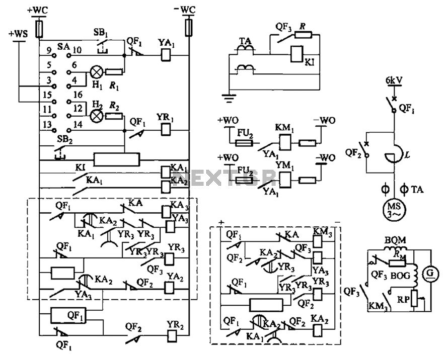
The circuit depicted in Figure 3-189 includes various components such as switch SA, closing button SBi, trip button SBz, de-excitation switch Yaa, and off trip coil YR3. The excitation switch contacts are represented by QF3, which serves as a...
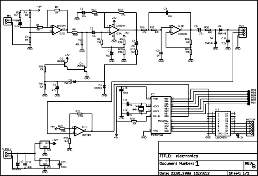
External circuit converts bass beat of music into pulses. The motor is controlled by them. If there's bass beat recognized then the motor rotates one direction (in full stepping) for a predefined time then stops. If the second beat...