
50 MHz frequency counter voltage meter & SWR/PWR indicator

The circuit design of the frequency counter and voltmeter features an integrated approach utilizing the PIC16F876 microcontroller, which combines multiple functions into a single chip, thereby reducing component count and overall size. The microcontroller's ability to drive a multiplexed 4-digit LED display allows for efficient visual feedback of the measured values. The design also incorporates analog input channels for measuring SWR (Standing Wave Ratio) and power levels, which are processed by the microcontroller and output as a bar graph representation on the display.
The user interface is designed for ease of operation, with a simple push-button switch enabling the selection of display modes. This intuitive design allows users to toggle between frequency readings, voltage measurements, and bar graph displays of signal strength without needing to navigate complex menus. The ability to adjust the frequency display format enhances usability, providing flexibility based on user preferences.
The choice of LED displays is critical, especially given the discontinuation of the HDN1077 models. The new HDSP-U103 displays not only maintain compatibility with the existing PCB layout but also improve power efficiency, which is vital for portable applications. The design ensures that the average current draw remains low, optimizing battery life during operation.
The programming capabilities of the PIC16F876 allow for future updates and enhancements, ensuring the device remains relevant and functional. The recommendation to install the MC34064 reset circuit after testing underscores the importance of maintaining stability in the system, particularly in environments where power fluctuations may occur.
Overall, the design reflects a modern approach to electronic measurement devices, prioritizing efficiency, usability, and adaptability to meet the needs of radio amateurs and other non-commercial users.This is a successor of the PIC16C71 4-digit LED f-counter & V-meter. Some hard to find parts used in the previous version, which are out of production for some time, has been omitted. A rather early PIC16C71 has also been replaced by 28-pin device PIC16F876. The later is capable of driving 4 digit LED display in multiplexed mode while measuring fr equency, power supply voltage as well as handle two analog inputs to display SWR/PWR signal strength in a bargraph manner. There is no need for external LED display driver chip as well as external data EEPROM since it is already implemented in PIC16F876.
Reduction in the number of used chips also results in smaller dimensions of the counter compared to its predecessor. In operating mode a push-button allows the user to choose between the frequency, bargraph or supply voltage to be displayed.
The frequency display mode can also be changed with longer (>1s) push-button pressing. For example if the frequency to be displayed is 14. 065. 9 MHz the user will see on the four digit display either 065. 9 ³, 4. 065 ³ or 14. 06 ³. The default display mode after power-up can be changed in the set-up menu. The set-up menu is entered at power-up while holding the push-button pressed. The production of Siemens`s (now Infineon`s) miniature 7 seg. LED HDN1077 displays in low current version (suffix O) was abandoned recently. Therefore I`ve designed another display PCBoard which suits the same f-counter base board but uses newer Agilent`s HDSP-U103 miniature 7 seg. LED displays. Their current consumption is even smaller. They need no more than 0, 5mA per segment for acceptable brightness. Assuming that during normal operation in average only one half of the segments lights, the average current consumption of the counter is about 20mA.
In power-save mode the consumption reduces to less than 10mA which is important in case of battery powered equipment. The latest software version of the frequency counter is for radio-amateur and non-commercial use downloadable from this page for free.
The PIC controller is in-circuit programmable if the MC34064 reset circuit is not soldered to the PCB. The instalation of this IC is strongly recommended after the frequency counter has been built and tested.
🔗 External reference
Related Circuits
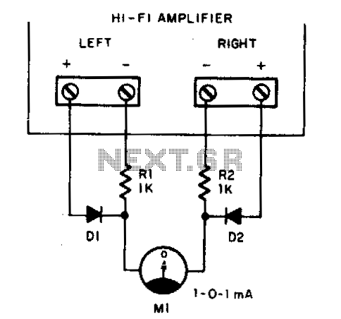
Play any stereo disc or tape and then set the amplifier to mono. Adjust the left and right channel balance until meter Ml indicates zero; then the left and right output levels are identical. To implement a system that allows...
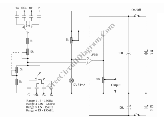
This sine wave generator is adjustable between 15 Hz and 150 kHz. The circuit is essentially a Wien-bridge oscillator, featuring multiple capacitor selections. The sine wave generator operates on the principle of the Wien-bridge oscillator, which is known for producing...
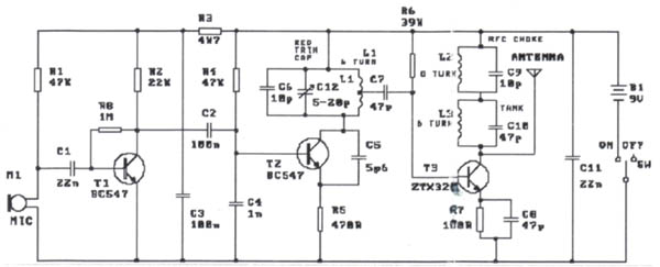
The modification presented involves using a 2N2219 NPN transistor to replace T2 and a 2N3553 NPN transistor to replace T3. Both transistors are categorized as VHF transistors. It is necessary to attach a heatsink to the last transistor. No...

The circuit utilizes a transistor (VT) and a voltage regulator (VSL) to create a constant current source, employing three regulators to enhance the performance of the regulator circuit. The described circuit employs a transistor (VT) in conjunction with a voltage...
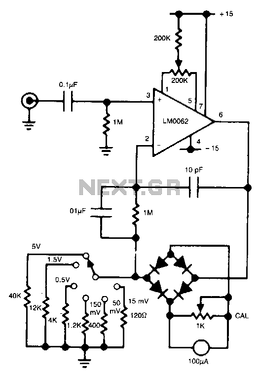
In this circuit, a diode bridge is utilized as a meter rectifier. The offset voltage is compensated for by the operational amplifier, as the bridge is part of the feedback network. The circuit employs a diode bridge rectifier, which consists...
The ammeter measures currents ranging from 100 pA to 100 µA without the need for costly high-value resistors. Accuracy at 100 µA is constrained by the offset voltage between Q1 and Q2, while at 100 pA, it is limited...