
5000W ultra-light high-power amplifier without switching-mode power supply

This circuit design features a dual-channel amplifier capable of delivering 2x 500W RMS output. The architecture is lightweight, making it suitable for portable applications, and it intentionally avoids the complexities and weight associated with traditional switching-mode power supplies. The schematic primarily illustrates one channel, with the understanding that a second identical circuit is to be replicated for stereo functionality. The power supply is engineered to efficiently support both channels, ensuring reliable performance.
Critical to the circuit's operation is the selection of a high-quality insulating transformer. This component is essential for maintaining audio fidelity and minimizing noise, particularly in sensitive audio applications like microphone preamps. The transformer should be rated for audio applications to ensure optimal performance.
The combined power output of the amplifier is rated at 5,000W RMS, making it suitable for various amateur audio setups, such as home theaters or live sound reinforcement. The design emphasizes portability, with the entire assembly, including the power supply and amplifier circuits, weighing no more than 32 lbs when enclosed in a robust metallic chassis. This weight consideration is crucial for users who may need to transport the amplifier frequently.
Safety is a paramount concern in this design. The circuit contains components that are not isolated from the AC mains, which introduces risks of electric shock. Users must exercise caution when handling the device, particularly when connecting speakers, as these connections are also not isolated from the domestic AC network. It is imperative to implement safety measures to mitigate these risks, especially in amateur applications where users may lack extensive electrical knowledge.
This circuit represents an innovative approach to audio amplification, prioritizing weight and cost efficiency while maintaining performance. However, it is essential to note that the design may not comply with commercial regulations in certain jurisdictions, and users must assume responsibility for the application of this circuit.This circuit is of an 2x 2, 500W RMS stereo amplifier, super-light and without switching-mode power supply. The circuit just shows a channel, and the power supply that it assists to the two channels. The audio circuit should be duplicated, but the power supply assists to the two channels without problems.
A special care should be destined to the in sulating transformer of the audio line, that should be of audio-high-quality, of the type used in microphone pre amps input line. The whole group (2 channels) of 5, 000W RMS it should not weigh more than 32 lbs, already inside of an appropriate metallic box.
This circuit is exclusively for amateur use. It contains not-isolated parts of the electric AC net and it can be very dangerous. The connections for the speakers are not isolated of the domestic AC net and it requests extra care. This procedure seeks to substitute a conventional power supply with great weight and cost reduction, without necessarily to use a switching-mode power supply. This procedure cannot be allowed in some countries for commercial-use. The author doesn`t have any responsibility for the form as that circuit it will be applied. 🔗 External reference
Related Circuits
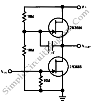
This is a simple high-gain JFET audio amplifier circuit. This circuit requires very low power but provides a high-gain amplification function. It is also referred to as JFET. The JFET (Junction Field Effect Transistor) audio amplifier circuit is designed to...
A common collector amplifier circuit structure and its key components are outlined. The composition of the common collector amplifier circuit is fundamentally similar to that of a common emitter amplifier circuit, with two notable exceptions: one is the collector...
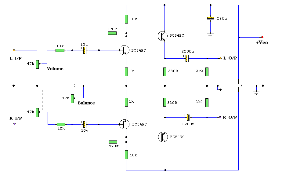
Both halves of the circuit are identical. Both inputs have a DC path to ground via the input 47k control, which should be a dual logarithmic type potentiometer. The balance control is a single 47k linear potentiometer, which, when...
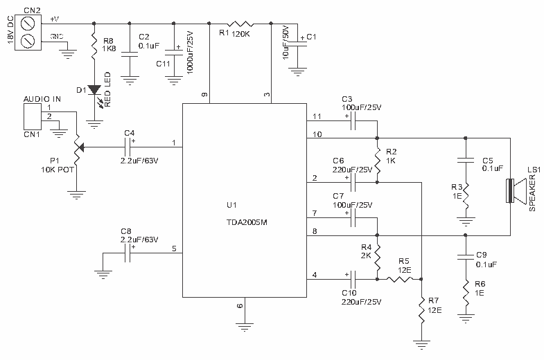
20W Bridge Audio Amplifier kit, based on the TDA2005 IC, a class B dual audio amplifier, specifically designed for car radio applications etc. More: Power supply - 18 VDC Output power - 20 W, 4 Ω IC built in Thermal Shut-down,...
MC44BS373CA: PLL Tuned UHF and VHF Audio Video High Integration Modulator MC44BS373CA The MC44BS373CA Audio and Video Modulator is designed for use in VCRs, set-top boxes, and similar devices. Manufactured by Freescale Semiconductor, Inc. The MC44BS373CA is a highly integrated...
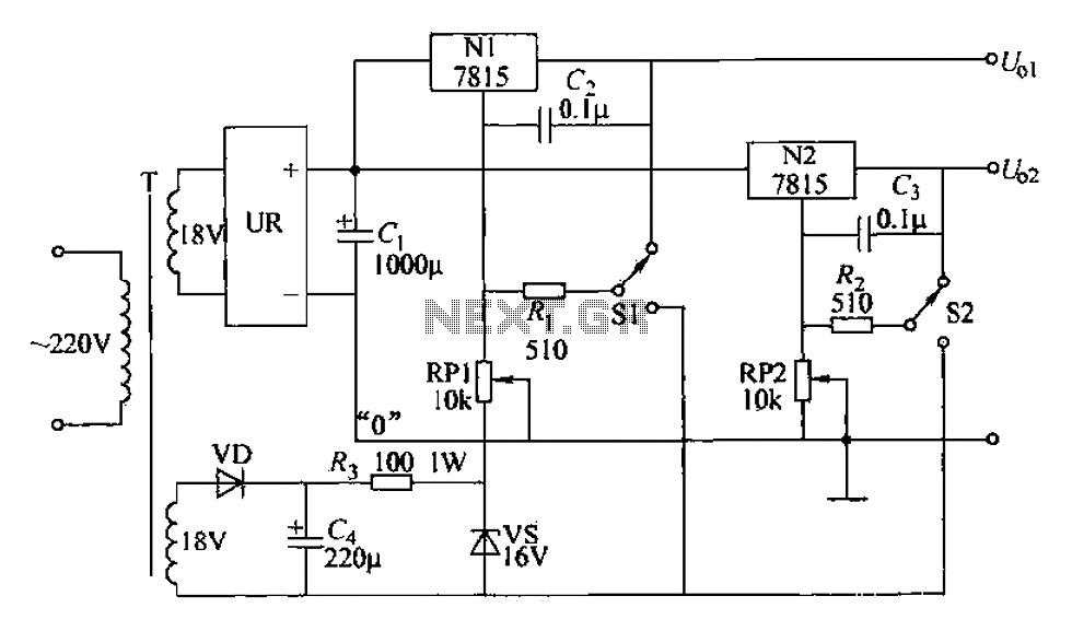
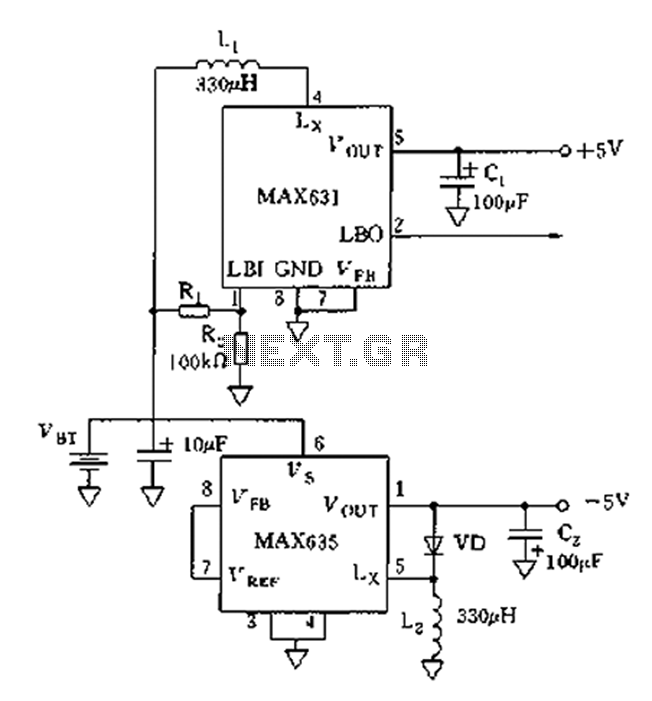
An adjustable dual voltage power supply circuit is presented, suitable for frequent experimental use. The current output does not exceed 1A, and both voltage outputs are adjustable. The circuit utilizes N1, N2, and 78 series three-terminal voltage regulator integrated...