
500mW Broadcast FM Transmitter

This FM transmitter circuit is designed to provide a reliable and efficient means of broadcasting audio signals over short distances. The four-transistor configuration allows for effective amplification and modulation of the RF signal. The use of a class D amplifier in the output stage contributes to high efficiency, minimizing power loss and heat generation, which is particularly beneficial in battery-operated applications.
The transmitter operates in the VHF band, specifically around 100 MHz, which is suitable for many audio broadcasting applications. The frequency can be fine-tuned by adjusting the coil, allowing for flexibility in operation and enabling users to avoid interference with other radio services. The audio modulation is accomplished through a combination of the 5 pF capacitor and the 10K ohm resistor, which form a coupling circuit that feeds the audio signal into the tank circuit, ensuring that the modulation is effectively applied to the RF carrier wave.
The 1N4002 diode plays a crucial role in managing the modulation depth, ensuring that the audio signal is rectified properly, which aids in maintaining signal integrity. The overall design prioritizes simplicity and effectiveness, making it accessible for hobbyists and professionals alike. The compact nature of the circuit also allows for easy integration into various devices or systems requiring FM transmission capabilities. The careful selection of components ensures that the transmitter operates efficiently within the specified power range, making it suitable for various applications, including personal broadcasting and experimental radio projects.This little broadcast FM transmitter has 500mW of RF output power and runs of 12-15V battery or power supply. DC whose signal modulated by FM using four transistors. Transmitter includes four transmitter stages and draws around 100-150mA of current. Using the values of the circuit components, the frequency will be around 100 MHz but can be changed via coil.
Through the 5 pF capacitor and 10K ohm resistor, the modulation of audio signal is supplied to the tank circuit. The amount of modulation is being managed by the 1N4002, a general purpose rectifier diode. FM Transmitter`s output stage is functioning as a class D amplifier where the output transistors act as a switch.
. 🔗 External reference
Related Circuits
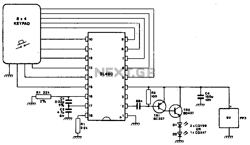
This simple infrared transmitter uses the PPM output from pin 2 of the SL490, which is connected to the base of the PNP transmitter TR1. It generates an amplified current pulse approximately 15 microseconds wide. This pulse is further...
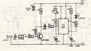
This infrared transmitter utilizes pulse width modulation (PWM). The transmitter is equipped with an LM567 tone decoder circuit. An audio signal (at least 50 mV peak-to-peak) is amplified with transistor T1 and subsequently used to modulate IC1. The frequency...

3V FM Transmitter Circuit. This project provides the schematic and the parts list needed to construct a 3V FM transmitter. This FM transmitter is... The 3V FM transmitter circuit is designed to operate at a low voltage, making it suitable...
In the past, when AM radio was dominant, significant resources were allocated to the development of transmitting equipment. The GE BTA-25 transmitter from that era exemplified this commitment, featuring a robust construction. During a repair of the Harris MW-50A...
This transmitter emits an FM signal within the 88 to 108 MHz frequency range, featuring a tone of 19 kHz. This tone can activate the FM MPX pilot carrier indicator, allowing interfacing with external devices. L4 is designed for...
This AM transmitter design is notably simple to construct due to its use of a non-tapped inductor featuring a single winding. The inductor can be conveniently sourced as a standard RF choke, such as the Jaycar Cat LF-1536. To...