
50MHz crystal bug

L2 and C2 assist in clarifying the 47MHz signal. L2 should be between 300-700nH and is also a tunable coil. C1 and C2 should be in resonance at 47MHz. In one construction, L2 was measured at 476nH and C2 at 10pF. The FET transistor serves as a voltage follower with a very high input impedance and low output impedance. An oscilloscope can be connected to the source of the BF245B to observe a significantly improved 47MHz signal. Tuning L2 and C2 will enhance the signal's shape and amplitude. L1 and C1 should also be tuned for optimal performance.
The final stage consists of a power amplifier that requires no tuning. Various types of transistors can be utilized, with the BFG97 providing satisfactory power levels. A potentiometer, P1, can be used to adjust the current in the transistor, and experimentation is necessary to determine a suitable working current. Replacing this potentiometer with a 7.5k resistor has been noted. Resistor R2 can also be adjusted; lower values increase current consumption and output power.
Fine-tuning of the transmitting frequency is achieved with L3, another tunable coil. The inductance of L3 can vary from 2-8µH, with an experimental value of 6.8µH at 50MHz. Experimentation is required to find the optimal inductance range for the transmitter. Connecting a frequency counter to the output will assist in tuning L1 to the desired frequency, allowing for a frequency change of approximately 100kHz. To match the receiver, the transmitter should be tuned until the best signal is received, indicating that both units are aligned. C3 and C4 should be tuned for maximum output power.
Two NPN transistors (BC817) function as amplifiers, amplifying audio from the microphone. The voltage to the varicap is approximately 750mV DC, while the audio signal is around 500mV AC.This bugg is based on my previous 3-transistor transmitter. This bugg unit has many advantage. The transmitter use a crystal 46.515MHz to hold a steady frequency. The frequency can be fine-tuned by some 100kHz. The transmitter can send data and audio-signal with +/- 10kHz FM modulation. The output power is about 10mW into 50 ohm. The crystal I used is a 3:th overtone crystal. The coil L1 is a slug tuned coil. The primary winding is 8 turns and the second winding is 2 turn. The inductance in the primary winding is about 800nH. L1 and C1 should be in resonance at 47MHz. The number of turns is dependent on type of coil you have. You will have best performance when the "ferrite tuning slug" is at the bottom of the CAN, because you will then have the best couppling between the two windings. Wind primary and secondary winding on the core and turn the slug to the bottom of the CAN. If you can, measure the inductance in the primary winding. It should be around 800nH. Attach a oscilloscope to the colector of the NPN transistor or to the second winding. You should see an oscillation. Tune C1 until you find the 3:d overtone. You won't get a perfect signal at 47MHz. You will probably find a very jumpy signal because of other harmonic frequencies. Don't mind that, just try to tune until you find some proper signal, anyhow you will know that the oscillator works. L2 and C2 help to clear up the 47MHz signal. L2 should be 300-700nH also a tunable coil. C1 and C2 should be in resonans at 47MHz. I measured L2 and C2 in my construction and come upp with L2=476nH and C2=10pF. The FET transistor is a voltage follower with very high imput impedance and low output impedance. You can attach an oscilloscope at the source of BF245B. You should find a much better 47MHz signal here. Now, tune L2 and C2 until you reach a nice shaped signal with max amplitude. Tune also L1 and C1 for best performance. The last stage is a power amplifier. This unit doesn't need any tuning. I guess you can use many different type of transistors here. I have used the BFG97 and it gives quit good power. I haven't been experimenting much with other types. With P1 you can set the current in the transistor. You will have to experimient to find a suitable working current. I replaced this pot with a resistor of 7.5k. You can also experimtent with resistor R2. The lower value the higher current consumption and the more output power. The finetuning of the transmitting frequency is made with L3. This is also a tunable coil. The inductance of this coil can be changed from 2-8uH. The exact value of L3 at 50MHz was 6.8uH in my experiment. You will have to play a bit to find the best inductance range for you transmitter. Just connect a frequency counter to the output and tune L1 to the desired frequency. You can easy change the frequency some 100kHz. To match the receiver you should start the receiver and then tune the transmitter until you reach the best signal from the receiver, then you will know that the two units are in perfect match.
Tune C3, C4 for best output power. The two NPN transistors (BC817) works as amplifiers. They amplify the audio from the mic. The voltage to the varicap is about 750mV DC and the audio-signal is about 500mV AC. 🔗 External reference
Related Circuits
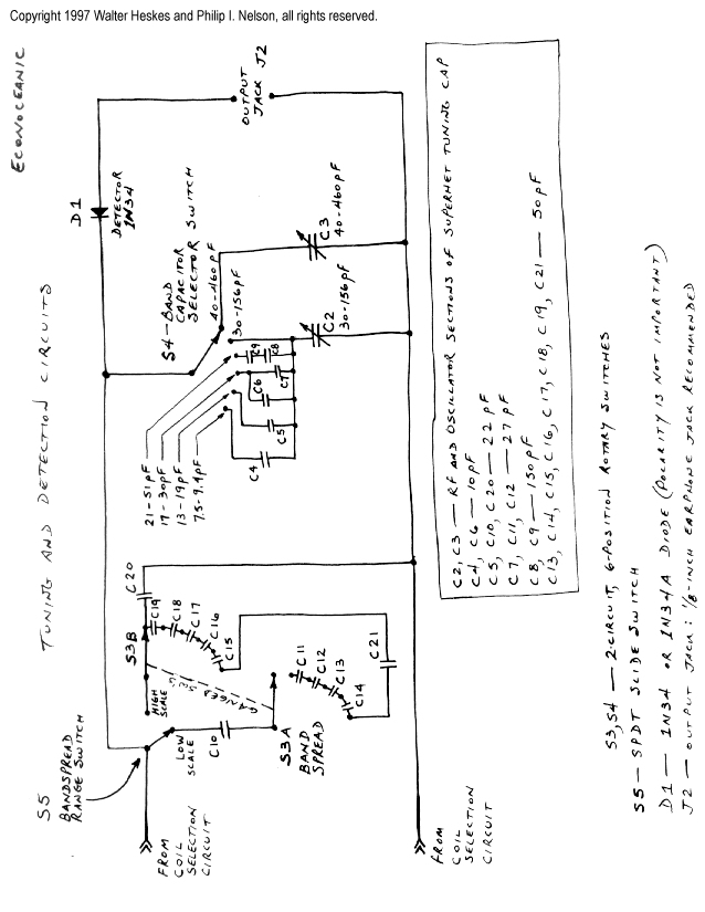
This project merges two significant themes from radio history: crystal radios and shortwave (SW) listening. It has been developed from the ground up by non-resident engineer Walter Heskes. Despite advancements in modern electronics, numerous crystal sets are actively used...
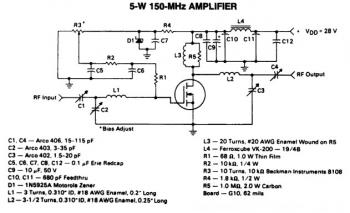
This is a 5W -150MHz RF amplifier circuit that utilizes the MRF123 TMOSFET. The MRF123 is a high-gain FET which may exhibit instability at both VHF and UHF frequencies; therefore, a 68 Ohm input loading resistor is employed to...
This LCD terminal provides two modes of operation by selecting jumper J1. When J1 is open, the terminal operates as a normal ASCII display terminal. When J1 is closed, the terminal displays the input serial data in hexadecimal format....
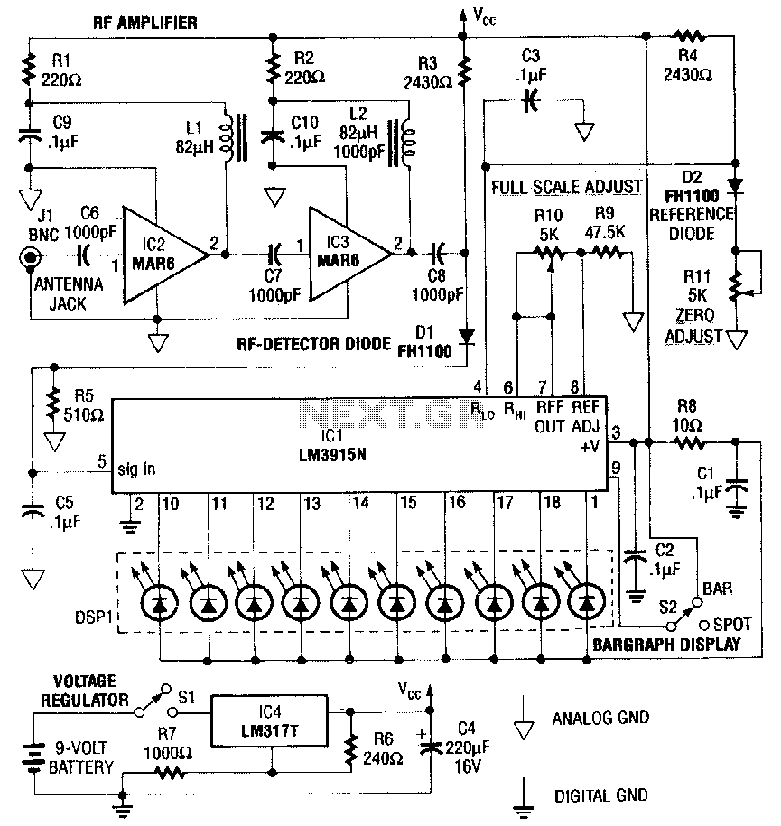
This RF detector is capable of locating low-power transmitters (such as bugs) that are not visible. It can detect the presence of a 1-mW transmitter from a distance of 20 feet, making it sensitive enough to identify even the...
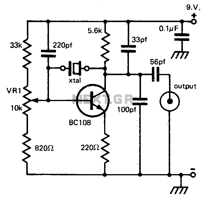
This circuit provides reliable oscillation and an output close to one volt peak-to-peak. Power consumption is around 1 mA from a nine-volt supply. The described circuit is likely a simple oscillator designed to generate a periodic waveform with a peak-to-peak...
Last year, I found a 31 day pendulum wall clock (disassembled) in a box of parts at a swap meet and decided to try and put it together and regulate it with a quartz crystal oscillator. The escapement part...