
Spot lamp dimmer by LM555 and TIP2955

The DC dimmer circuit employs the LM555 timer IC, which is a versatile component widely used in various electronic applications. In this configuration, the LM555 operates in astable mode, generating a continuous square wave output. The frequency and duty cycle of this waveform can be modified by adjusting the values of the resistors VR1 and VR2, which are connected to the timing capacitor.
The operation of the circuit is based on the charging and discharging cycles of the capacitor connected to the LM555. As the capacitor charges through VR1 and discharges through VR2, the time periods for both processes determine the duty cycle of the output signal. A higher resistance in VR1 will increase the charging time, resulting in a longer "on" time for the output signal, thereby dimming the connected load. Conversely, adjusting VR2 will influence the discharging time, further fine-tuning the dimming effect.
This circuit can be applied to control the brightness of DC loads such as LED lights, allowing for energy-efficient operation and user-customizable lighting levels. To ensure stability and performance, it is important to select appropriate values for the timing components, considering the specifications of the load being controlled. Additionally, the circuit may include protection elements like diodes to prevent back EMF from inductive loads, ensuring the longevity of the LM555 and other components used in the circuit.This circuit is DC Dimmer Circuit. By use IC LM555 be model Astable Multi vibrator. It is can change translate Duty Cycle with fining VR1 and VR2 be.. 🔗 External reference
Related Circuits
This simple circuit, as shown in the schematic diagram, activates a switch using sound. It can be utilized for various applications, such as automatic sound-controlled disco lights or a car's LED light show. The transistor Q1 amplifies the audio...
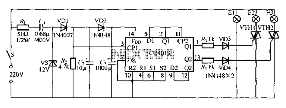
Figure 296 illustrates a control circuit that utilizes a switch (S) to manage three lamps (E1, E2, and E3) in a lighting system, suitable for controlling a chandelier in a living room. When the switch is off, all lights...

The IR2156 provides a cost-effective solution for fluorescent electronic ballasts. It integrates features such as lighting tube error protection and a programmable working frequency, which includes warm-up, lighting, and continuous operation of the ballast. The IR2156 is a highly integrated...

This simple circuit shown in the schematic diagram activates the switch using sound. This circuit can be used for various applications, such as automatic switching. The circuit utilizes a sound sensor, which is typically a microphone or a piezoelectric sensor,...
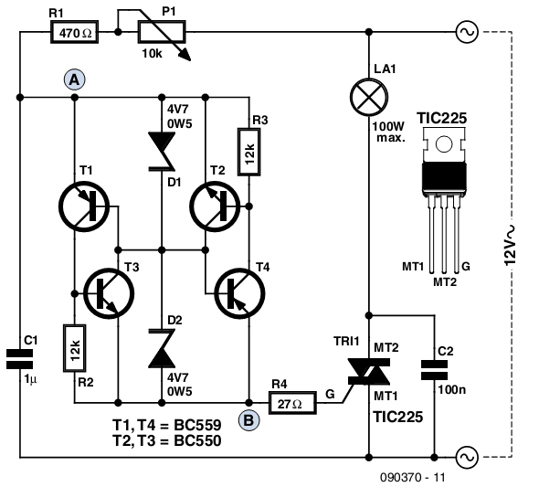
The circuit presented is based on a conventional design for a simple lamp dimmer, featuring a diac connected between points A and B. Unlike standard diac circuits that require a trigger voltage of 30 to 40V, this design operates...
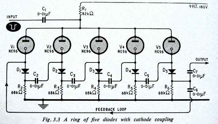
The above shows a home-built digital clock that utilizes Nixie tubes for display. Unlike most contemporary Nixie clocks, this design does not employ transistors or integrated circuits for driving the tubes. Instead, the driving logic is constructed using neon...