
555 ASTABLE_FREQUENCY METER

This digital frequency meter circuit employs a 555 timer in astable mode, which generates a continuous square wave output. The frequency of this output can be measured and displayed using the accompanying circuitry. The primary components include two NPN transistors, TR1 and TR2, which play crucial roles in signal amplification and processing.
Transistor TR2 is directly connected to the output of the 555 timer. It serves to buffer the signal and provide necessary isolation from the timer circuit. The output from TR2 is then fed into the collector of TR1, which is configured as a switch. When the output from TR2 exceeds a certain threshold, TR1 activates, allowing current to flow through the main circuit, which may include a digital display module or a frequency counter.
The frequency meter's design can be adapted for various applications beyond measuring the frequency of a 555 timer. For instance, with appropriate modifications, it can be used to measure other digital signals or even analog signals converted to a digital format. The output signal's characteristics can be tailored by adjusting the resistor and capacitor values in the 555 timer circuit, thereby changing the frequency range of the meter.
Additionally, the circuit can be enhanced with features such as a calibration mechanism, allowing for accurate frequency readings across a wider range. Implementing a microcontroller could also facilitate more advanced functionalities, such as data logging or interfacing with other digital systems for automated frequency measurement tasks.
Overall, this digital frequency meter circuit provides a versatile platform for frequency measurement, with the potential for various modifications and enhancements to suit specific requirements.The circuit shown is a simple digital frequency meter, which indicates the frequency in hertz of an astable 555 timer. It could, perhaps, be adapted for other uses. An NPN transistor, TR2, is connected to the 555 astable to be measured, as shown in the in-set, and the output signal obtained is hooked to the main circuit via transistor TR1 collector (c)..
🔗 External reference
Related Circuits
If this picture above looks a lot like the Pretty Good LC Meter also on this web site, that's because it's the same meter, but with some significant improvements. At this point, it's a good idea to read the...
To achieve a lower parts count than the two-transistor multivibrators, two LEDs can be alternately flashed using a 555 integrated circuit configured as illustrated in Schematic 2. A combination of a 2.2kΩ and a 47kΩ resistor is used to...
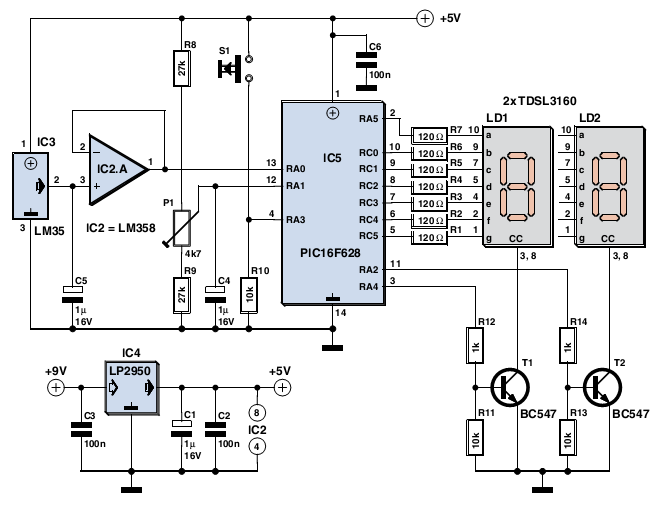
The device is user-friendly and consumes minimal current, allowing it to operate throughout the battery's shelf life. It employs a standard LM35DZ sensor (IC3) whose analog output voltage is buffered by an LM358 (IC2A). The voltage is processed by...
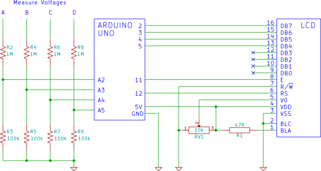
An Arduino voltmeter that displays voltage on an LCD display. The voltmeter has 4 channels for measuring four different voltages. The Arduino voltmeter utilizes an Arduino microcontroller to measure and display voltage levels on a Liquid Crystal Display (LCD). This...

In this circuit, A = 1, port = 0.5, and it features a passive vent filter without distinction. Attention is required when the circuit is dry; Q is determined by the formula Q = 1 / (3 - A)....
This Field Strength Meter is simple and also quite sensitive. It uses an ordinary digital voltmeter to measure RF signal strength up to a few hundred MHz. The multimeter should be set to the lowest dc volts range for...