
Simple Field Strength Meter

The described Field Strength Meter is a straightforward yet effective device designed for measuring radio frequency (RF) signal strength in the VHF range, particularly around 100 MHz. The circuit utilizes a standard digital voltmeter (DVM) as the primary measurement tool, capitalizing on its ability to provide precise voltage readings.
To achieve optimal sensitivity, the DVM must be configured to the lowest available DC voltage range, typically 200 mV DC. This setting allows the meter to detect minute variations in RF signal strength, which is critical for applications such as antenna tuning, signal testing, and troubleshooting in RF circuits.
The core of the circuit includes an inductor, labeled L1, which is constructed with 7 turns of wire wound on a quarter-inch diameter former. The use of a ferrite slug within the inductor enhances its inductance and improves its performance at RF frequencies. The design of the inductor is crucial, as it directly influences the meter's sensitivity and frequency response.
In practical application, the Field Strength Meter can be employed to gauge the strength of various RF signals, facilitating the alignment and optimization of antennas and other RF components. The simplicity of the design ensures that it can be easily assembled and utilized by both hobbyists and professionals in the field of electronics and telecommunications. Overall, this device serves as an invaluable tool for anyone working with RF signals in the specified frequency range.This Field Strength Meter is simple and also quite sensitive. It uses an ordinary digital voltmeter to measure RF signal strength up to a few hundred MHz. The multimeter should be set to the lowest dc volts range for maximum sensitivity. This is normally 200mV DC for most meters. The circuit works well at VHF (around 100MHz) and was quite pleased with the results. L1 was 7 turns on a quarter inch former with ferrite slug. 🔗 External reference
Related Circuits
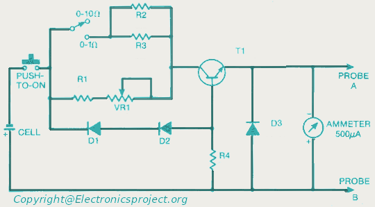
This document provides a circuit diagram for an ohmmeter designed for low resistor measurements. Additional resources, including over 300 electronic circuits, are available on this site. The ohmmeter circuit is primarily used to measure the resistance of low-value resistors, typically...
This is a 7-digit frequency meter measuring frequency from 10 Hz up to 1300 MHz. It is based on ideas of PIC16F84 based frequency meter. The measuring range is divided into two subranges: 10Hz - 25MHz and 25 MHz...
I like to see lights move to music. This project will indicate the volume level of the audio going to your speakers by lighting up LEDS. The LEDS can be any color so mix them up and really make...
The circuit illustrated is a straightforward digital frequency meter that displays the frequency in hertz of an astable 555 timer. It may potentially be modified for alternative applications. An NPN transistor, TR2, is linked to the 555 astable timer...
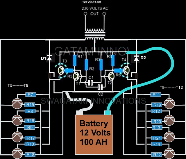
The current design of a power inverter offers an efficiency of approximately 85% and a power output exceeding 200 watts. This document provides a complete circuit schematic and detailed building procedure for a home-built power inverter. While numerous articles...
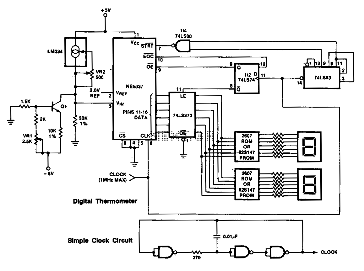
This circuit utilizes a +5 V reference output and an operational amplifier (op amp) to level shift and amplify the 2.1 mV/°C Tempco output into a voltage signal that varies with ambient temperature. Different scaling options can be achieved...