
555 timer voltage controlled oscillator

The voltage-controlled oscillator (VCO) circuit described operates by leveraging the 555 timer's capability to function as an astable multivibrator. In this configuration, the 555 timer generates a continuous square wave output, which is characterized by its frequency and duty cycle. The frequency of oscillation can be finely tuned by adjusting the voltage applied to pin 5, the control voltage input. This feature is particularly useful in applications where precise frequency modulation is required, such as in signal generation, tone generation, or in communication systems.
The circuit typically consists of resistors and capacitors connected to pins 6 and 2, which determine the timing intervals for the output pulse generation. The external voltage applied to pin 5 is critical as it modifies the reference levels for the internal comparators, which compare the voltage at pins 2 and 6 to determine the state of the output. The relationship between the control voltage and the output frequency is inversely proportional; thus, careful selection of the external voltage source can achieve the desired frequency range.
In practical applications, the VCO can be used in various electronic devices, including frequency synthesizers, modulated signal generators, and audio tone generators. The design allows for easy integration into larger systems, providing a reliable method for frequency control. The simplicity of the 555 timer circuit, combined with the versatility of the control voltage input, makes it an attractive choice for engineers seeking to implement a voltage-controlled oscillator in their designs.This is a circuit of a voltage-controlled oscillator (VCO) that uses the 555 timer IC as the main component. As expected, the 555 timer is configured as an astable multi vibrator to be able to serve as an oscillator.
An astable multi vibrator is just a timing circuit whose output oscillates between `low` and `high` continuously, in effect generati ng a train of pulses. This is the figure of the circuit; The difference of this circuit with the basic 555 astable circuit is that its 555`s pin 5 is tied to an external voltage source. Pin 5 is the 555`s control voltage pin, which allows the user to directly adjust the threshold voltages to which the pin 2/pin 6 input voltages are compared by the 555`s internal comparators.
Since the outputs of these comparators control the internal flip-flop that toggles the output of the 555, adjusting the pin 5 control voltage also adjusts the frequency at which the 555 toggles its output. Increasing the input voltage at pin 5 decreases the output oscillation frequency while decreasing the input voltage increases the output oscillation frequency.
🔗 External reference
Related Circuits
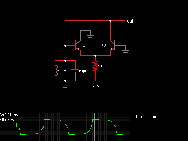
When the oscillator starts, Q2 is in a conducting state; the current flows from the capacitor, charging it until the voltage across it is sufficient to allow current to flow through the inductor. As the current through the inductor...
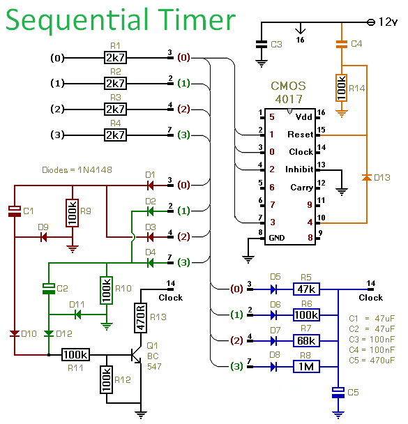
This circuit utilizes a CMOS 4017 decade counter to generate a sequence of four distinct events, with the capability to expand the sequence to nine or ten events. Each event's duration is independently controlled. The inclusion of D13 allows...
The foot 13 between valve value 1 and valve value 2 will draw the transistor base current. If the relay releases, after a recovery time of 0.5 seconds, pressing the key will initiate the switching process again. The timer...

This is a simple water level alarm circuit made using a 555 timer IC. The circuit will produce an alarm when the water level reaches a preset level. The water level alarm circuit utilizing a 555 timer IC is designed...
This is a voltage multiplier circuit. The first circuit is used to double a square wave (of any amplitude). However, there is a drawback of approximately 2V losses in the base-emitter. A voltage multiplier circuit is designed to increase the...
Crystals with higher frequencies than approximately 30 MHz are predominantly overtone crystals. These crystals are designed to operate at an odd multiple of their fundamental frequency. However, they do not resonate at their overtone frequency without assistance; the oscillator...