
555 low power timing circuit diagram

The 555 timer IC is widely utilized in various applications due to its versatility and ease of use. In a low power timing circuit configuration, the 555 timer can function in both astable and monostable modes, allowing it to generate precise timing intervals or oscillations.
In the astable mode, the circuit continuously oscillates between high and low states, producing a square wave output. This configuration requires two resistors (R1 and R2) and a capacitor (C1) connected to the threshold and discharge pins of the 555 timer. The frequency of oscillation and duty cycle can be calculated using the formulas:
Frequency (f) = 1.44 / ((R1 + 2 * R2) * C1)
Duty Cycle (%) = (R2 / (R1 + 2 * R2)) * 100
In monostable mode, the 555 timer generates a single pulse when triggered. The duration of the pulse is determined by a resistor (R) and a capacitor (C) connected to the timing pins. The pulse width can be calculated as:
Pulse Width (T) = 1.1 * R * C
To minimize power consumption, low value resistors and capacitors can be selected, and the timer can be powered using low voltage sources. Additionally, the use of bypass capacitors near the power supply pins can help reduce noise and improve circuit stability.
The application of the 555 low power timing circuit can be found in timer applications, pulse generation, LED flashing circuits, and many other timing-related tasks. Proper layout and grounding techniques should be employed to ensure optimal performance and minimize interference.555 low power timing circuit diagram The diagram is from the tech information of chinaicmart. IF for more detailed infomation of the circuit diagram.. 🔗 External reference
Related Circuits

This circuit is designed for an LM1893 power line modem, which facilitates information transfer between remote locations using the power mains. The LM1893 serves as a power line interface for half-duplex (bi-directional) communication of serial bit streams employing various...
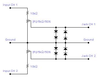
For simple electronic circuits, it may be sufficient to gain qualitative insights on dedicated electrical signals. This interface circuitry allows the line-in input of a standard PC sound card to be utilized as a 2-channel oscilloscope. Although this setup...
Typical segment display LEDs consume around 25 mA for each segment and should be limited to this current with resistors. For a six-digit display to be current limited, at least 42 series resistors are needed. The brightness of the...
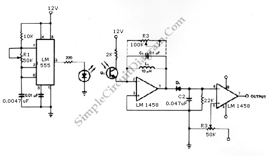
The infrared transmitter and receiver circuit depicted in the schematic diagram below can function as a remote control. The transmitter primarily operates as an oscillator. The infrared transmitter and receiver circuit is designed to facilitate wireless communication through infrared signals,...
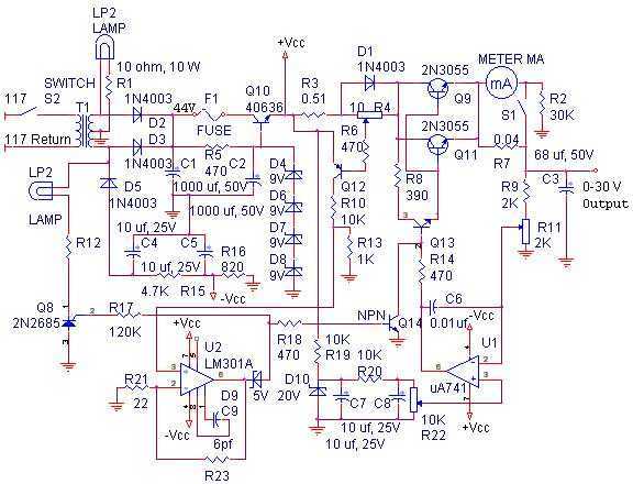
The linear power supply, shown in the schematic, provides 0-30 volts, at 1 amp, maximum, using a discrete transistor regulator with op-amp feedback to control the output voltage. The supply was constructed in 1975 and has a constant current...
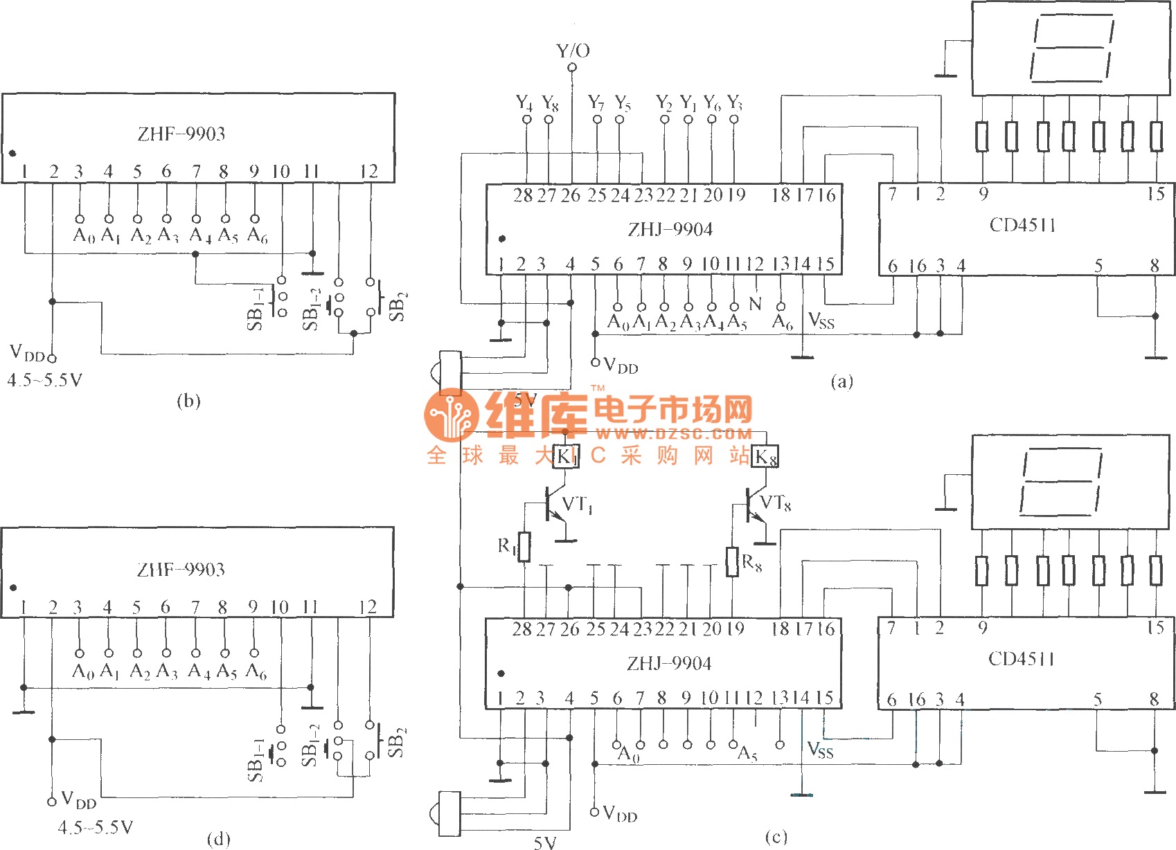
This is an eight-way signal remote control selection circuit composed of ZHJ-9904. It includes a remote control transmitter circuit, an eight-way switch control circuit, and a remote control transmitter. The eight-way signal remote control selection circuit utilizing the ZHJ-9904 is...