
555 configured as in this schematic

The circuit in question appears to deviate from the conventional astable multivibrator design, which typically consists of two resistors and two capacitors arranged to create a square wave output. In standard configurations, the timing components determine the frequency and duty cycle of the output waveform.
To analyze this non-standard configuration, it is essential to examine the components used, their connections, and the overall functionality. Non-standard configurations may include additional components such as diodes, additional transistors, or specialized capacitors that could alter the behavior of the circuit significantly.
The identification of the specific configuration may involve recognizing the role of each component within the circuit. For instance, if the circuit incorporates feedback loops or different types of transistors (such as MOSFETs or BJTs), it may suggest a unique application or modified operation mode.
Understanding the purpose of the circuit is also crucial. If it serves to generate specific waveforms, regulate voltage, or drive loads, this context can provide insights into its design rationale.
To facilitate better understanding, a detailed schematic diagram illustrating the connections and component values would be beneficial. This diagram should clearly label each component, including resistors, capacitors, and active devices, while also indicating the power supply connections and output terminals.
Overall, a thorough analysis of the circuit's behavior through simulation or practical experimentation may yield further insights into its operation and potential applications, enabling a comprehensive understanding of this non-standard multivibrator configuration.It is clearly not a standard astable multivibrator. Does nayone recognize this configuration? I would like to understand it better.. 🔗 External reference
Related Circuits
A metal detector utilizing the AVR Tiny13 microcontroller and a 555 timer IC to energize the coil, providing an output to the Tiny13 at pin 2 (CLK1). This circuit is designed to detect metals and magnets. The schematic includes...
An LED flasher circuit can be constructed using a 555 integrated circuit (IC). The use of the 555 IC allows for greater flexibility in adjusting the flashing rate of the LED. This LED flasher circuit is similar to other...

This circuit consists of four nearly identical debounced switches. Each switch features two resistors and one capacitor at the input of its respective Schmitt trigger, which are utilized for debouncing. The output from the Schmitt triggers is directed into...
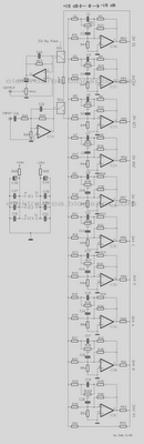
The diagram illustrates a circuit comprising 10 identical units, each varying only in the capacitance values of their capacitors, which determine the frequency band for each filter. Potentiometers are utilized to adjust the designated frequency regions in each unit....
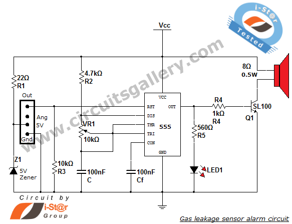
This article discusses a home security alarm circuit designed to detect LPG gas leakage. The circuit utilizes a gas sensor module, SEN 1327, which incorporates a QM 6 gas sensor. The output signal from this gas sensor module is...
The two unspecified polarized capacitors (one directly above the transformer and one directly to the right of the transformer) are actually each a pair of 470 µF capacitors in parallel (for a total of four 470 µF capacitors). These...