
Optical Direction Discriminator Circuit

The described circuit leverages the CD4001 NOR gate IC to create a simple yet effective rotational direction detector. The RS flip-flop serves as a memory element that retains the state corresponding to the direction of rotation, which is determined by the input pulse frequency and duty cycle. The integration of R1, C1, and D3 in conjunction with the NOR gate inverter is crucial for generating short pulses that are essential for accurate sampling of the flip-flop outputs.
In this arrangement, the first RS flip-flop captures the state of the incoming pulse stream, while the second RS flip-flop is used to provide a stable output indicating the direction of rotation. When the input pulses exhibit a high duty cycle, the resultant output from the first flip-flop leads to a consistent pulse train from the sampling NOR gate. This pulse train is instrumental in toggling the second RS flip-flop, ensuring that the output remains in a state that reflects the current rotational direction.
The circuit's design is particularly advantageous for applications requiring real-time monitoring of rotational motion, such as in motor control systems or rotary encoders. The use of standard logic components like the CD4001 allows for straightforward implementation and integration into larger systems. The simplicity of the design, combined with the reliability of the NOR gate logic, makes this circuit an ideal choice for detecting and indicating the direction of rotation in various electronic applications. The very simple circuit uses only two CD4001 packages, i.e., eight NOR gates and operates in the following way: Pulse streams are fed to an RS flip flop generating an output waveform wliich has a small or large duty cycle depending on the direction of rotation, The same input pulses are also fed to a NOR gate, which adds the two pulse trains. The rising edges of this waveform are used to produce short positive pulses from the circuit consisting of Rl, CI, D3, and a NOR gate used as an inverter.
This is used to sample the outputs of the flip flop to detect the direction of rotation. The output, whose duty cycle is large, forces the sampling NOR gate to generate a pulse train which sets (or resets) the second RS flip-flop continuously giving a permanent indication of the direction of rotation.
Related Circuits

A typical computer motherboard CPU power supply circuit is primarily composed of the main power supply management chip RT9241 and additional components from the power management chip RT9600. The voltage command signal from the CPU is input into the...
Some time ago, a request was received for the schematic of a circuit designed to detect cut phone lines. The circuit, sourced from Electronics Now, activates a MOSFET when it detects a cut in the phone line, which can...

This circuit consists of a 2 x 22 watt BTL amplifier utilizing the IC TA8210AH. It functions not only as an automobile amplifier but is also suitable for low-frequency sound applications, particularly in high-fidelity audio systems, due to its...
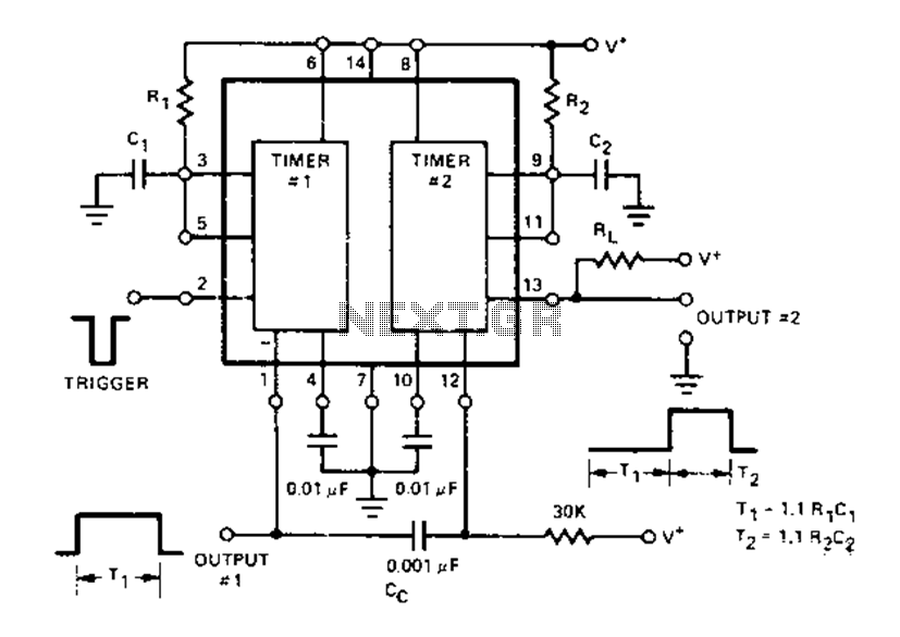
The Dual Timer Exar XR-2556 features a timing mechanism that can be triggered through capacitive coupling on a secondary timing pin. When a trigger input is engaged, the duration T1 can be set to 1.1R1C1, resulting in an increased...
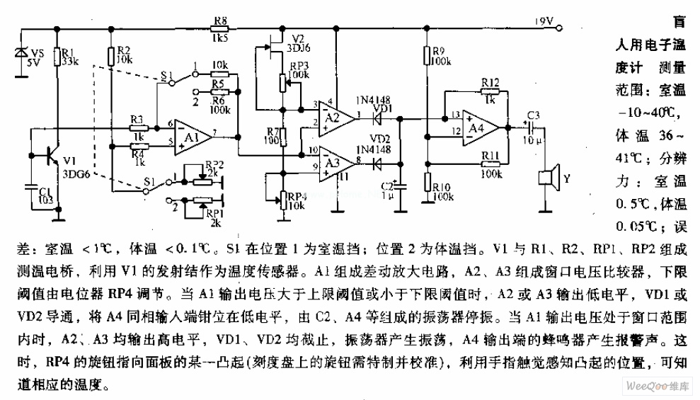
Measuring range: room temperature is -10 to 40 degrees Celsius; body temperature is 36 to 41 degrees Celsius; Resolution: room temperature is 0.5 degrees Celsius, body temperature is 0.05 degrees Celsius; error: room temperature <1 degree Celsius, body temperature <0.1 degrees Celsius. When switch S1 is in position 1, it displays the room temperature profile; position 2 displays the body temperature profile. Components V1, R1, R2, RP1, and RP2 form the temperature measurement circuit. The temperature measurement circuit is designed to monitor and display two distinct temperature ranges: ambient room temperature and body temperature. The circuit operates with a measuring range for room temperature from -10 to 40 degrees Celsius and for body temperature from 36 to 41 degrees Celsius. The resolution of the circuit is fine-tuned to provide accurate readings, with a room temperature resolution of 0.5 degrees Celsius and a body temperature resolution of 0.05 degrees Celsius. The specified error margins indicate a maximum deviation of less than 1 degree Celsius for room temperature measurements and less than 0.1 degrees Celsius for body temperature measurements. The circuit utilizes a switch, S1, which allows the user to select between the two temperature profiles. In position 1, the circuit outputs the room temperature, while in position 2, it outputs the body temperature. The operational components include a voltage source (V1), resistors (R1, R2), and potentiometers (RP1, RP2) that are integral to the measurement process. Resistors R1 and R2 are likely part of a voltage divider network that aids in scaling the temperature sensor output to a readable format. Potentiometers RP1 and RP2 can be used for calibration purposes, allowing fine adjustments to ensure that the readings are accurate within the specified error margins. The temperature sensor, which is not explicitly mentioned but is assumed to be part of the circuit, converts temperature changes into an electrical signal that can be processed by the circuit. The output from the sensor is conditioned by the resistive components to produce a voltage level that corresponds directly to the measured temperature. This voltage is then displayed on an appropriate display unit, which could be an analog gauge or a digital readout, depending on the design of the circuit. Overall, this temperature measurement circuit is a practical solution for monitoring both ambient and body temperatures with high accuracy and user-friendly operation through the selection switch.

This article outlines a lighting circuit designed to create a glowing firebox effect while providing constant illumination for classification lamps and an interior cab light. It includes comprehensive information necessary for constructing the circuit, such as a detailed schematic,...