
Audio Power Meter: Shows Your Audio Amplifier

The circuit for measuring amplifier output power typically includes a few essential components: a resistive load, a voltage divider, and a microcontroller or analog meter for display purposes.
To construct the circuit, first, select an appropriate resistive load that matches the impedance of the amplifier output, usually 4 or 8 ohms for audio applications. This load will dissipate the power generated by the amplifier, allowing for accurate measurement.
Next, a voltage divider can be employed to scale down the voltage across the load resistor to a level suitable for measurement. The voltage divider consists of two resistors; the values should be chosen based on the maximum expected output voltage from the amplifier to ensure that the scaled voltage does not exceed the input range of the measuring device.
The output from the voltage divider can be fed into either an analog voltmeter or an analog-to-digital converter (ADC) connected to a microcontroller. If using a microcontroller, the measured voltage can be processed to calculate the output power using the formula:
Power (P) = (V^2) / R
where V is the voltage across the load, and R is the resistance of the load. The microcontroller can then display the calculated power on an LCD or LED display for easy reading.
For enhanced functionality, the circuit can be designed with additional features such as peak hold, averaging, or even wireless transmission of the measurement data. Proper calibration of the circuit is essential to ensure accurate readings, which may involve using known reference signals or adjusting the voltage divider based on the specific characteristics of the amplifier being tested.
Overall, this circuit serves as a valuable tool for audio engineers and hobbyists alike, providing real-time feedback on amplifier performance and enabling optimization of audio systems.Using this circuit, you can measure the actual output power of your amplifier.? You can put this circuit in a box as a measurement instrument, or you can. 🔗 External reference
Related Circuits
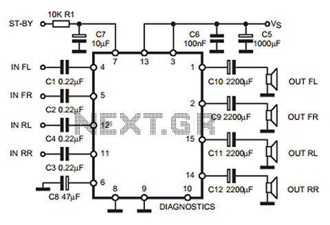
The following circuit illustrates a 35W quadruple amplifier and a 2 x 25W bridge amplifier based on the TDA7375 integrated circuit (IC). This circuit requires a minimal number of external components. Although initially designed for car applications, it can...
The 5W/6V solar panel can achieve a maximum current of approximately 500 to 800mA, peaking at 800mA during noon. Limiting the current to 150mA appears inefficient. A 1W panel can supply around 160mA during peak performance for up to...
This is an aerial current power supply with a continuously adjustable stabilized output ranging from 0 to 30VDC. The circuit also incorporates an electronic current limiter that effectively controls the output current from a few milliamperes (2 mA) to...
I designed this circuit for one friend of mine to be used as a small portable DJ mixer. The circuit is an audio mixer circuit so simple as it can be. There are two dual logarithmic potentiometers in the...
For some time, a variety of tape cassette decks have been available at low prices from mail order businesses and electronics retailers. These decks do not contain any electronics. Building a recording amplifier and the fairly complex magnetic biasing...
Most of the CDROMS available have an Audio-Out Output to either plug in the headphones or connect it to an amplifier. This circuit enables one to use the CDROM as a stand alone Audio CD player without the computer....