
555 Duty Cycle Control

The oscillator circuit utilizes the 555 timer IC configured in astable mode, which allows it to continuously oscillate between high and low states. The key feature of this design is its ability to adjust the duty cycle, which is the proportion of time the output is high compared to the total period of the oscillation, without changing the frequency of the output signal.
The circuit consists of a 555 timer, resistors, and capacitors. The frequency of oscillation is determined by the values of two resistors (R1 and R2) and a capacitor (C1) connected to the 555 timer. The duty cycle can be manipulated by varying the resistance of R2 while keeping R1 constant. This approach allows for a broad range of duty cycles to be achieved, making the circuit versatile for various applications.
In this configuration, the output frequency (f) can be calculated using the formula:
\[ f = \frac{1.44}{(R1 + 2R2) \cdot C1} \]
The duty cycle (D) is given by:
\[ D = \frac{R2}{R1 + 2R2} \]
By adjusting R2, the duty cycle can be varied while the frequency remains stable, provided that the capacitor value remains unchanged. This characteristic makes the circuit suitable for applications requiring pulse-width modulation (PWM) such as motor speed control, LED dimming, and signal generation.
It is important to select appropriate values for R1, R2, and C1 to achieve the desired frequency and duty cycle range. Additionally, the 555 timer should be powered with a suitable voltage supply, typically between 4.5V and 15V, to ensure proper operation. The output of the timer can drive loads directly or be interfaced with other circuit components for further processing.Here is a simple oscillator circuit that varies the duty cycle over a wide range without affecting the frequency. It is a variation of the simple 555 astab.. 🔗 External reference
Related Circuits
Good preparation. There is one suggestion to use RFM70 or RFM22 for RF communication. The RFM70 and RFM22 are low-power, high-performance RF transceiver modules designed for wireless communication applications. Both modules operate in the 2.4 GHz ISM band, making them...
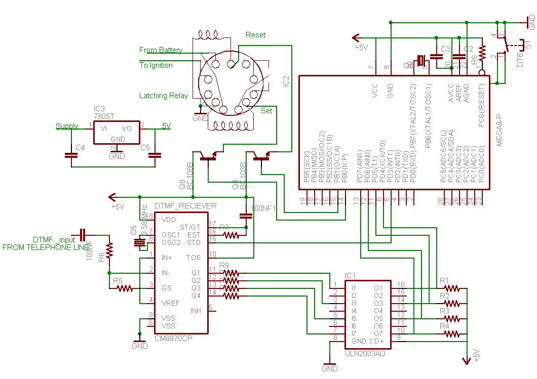
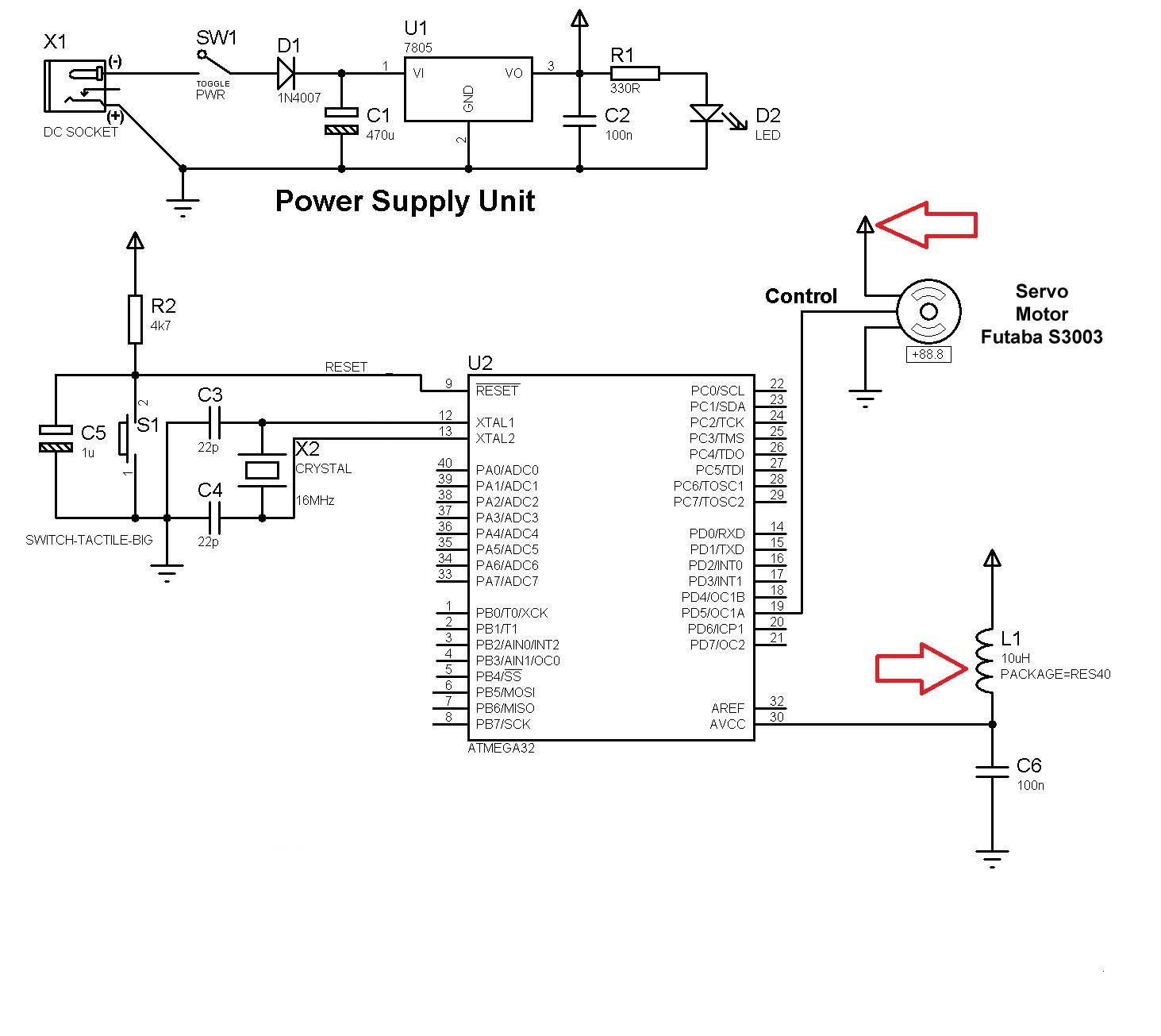
This document outlines the process of interfacing a microcontroller with a phone line. The tones generated when dialing numbers on a phone can be utilized to remotely control various devices. It provides guidance on incorporating Dual-Tone Multi-Frequency (DTMF) tones...
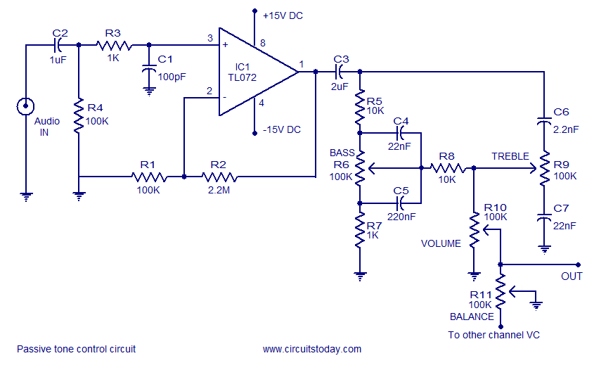
Tone control circuit utilizing an operational amplifier and a Baxandall passive tone control configuration. The overall gain is 25 dB, with a boost and cut capability of 20 dB. The circuit is powered by a dual 15V supply. The tone...
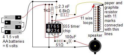
A simple music instrument/keyboard is created using a 555 timer chip circuit, a piece of paper, and a pencil. The project includes a more advanced automatic music player that utilizes a playing head and a long sheet of paper...
Diode D1 and resistor R1 provide VDD isolation during the programming of 24-pin devices. Jumper J3 must be shorted for 24-pin devices and left open for programming 28-pin devices. The following EEPROMs are pin compatible with their EPROM versions. In...
This project involves reading a thermistor using an Atmel ATtiny45 or ATMega168 microcontroller to control two fans for cooling a PC housed in a kitchen cabinet. A table is provided for converting the resistance of the BC1482 thermistor to...