
MOSQUITO REPELLANT by IC 555 4017 4011

The mosquito repellent circuit employs a high-frequency sound generator, which is designed to emit ultrasonic waves that are typically inaudible to humans but can deter mosquitoes. The core of the circuit is the 555 timer IC, configured in astable mode to produce a square wave output at a frequency that is effective for repelling mosquitoes. The frequency can be adjusted by changing the resistor and capacitor values connected to the 555 timer.
The output from the 555 timer is fed into a decade counter IC, the 4017, which can be used to drive multiple outputs. This allows for the possibility of connecting several ultrasonic transducers to enhance the coverage area of the mosquito repellent effect. The 4017 IC sequentially activates its output pins, which can be connected to different transducers, ensuring that the ultrasonic sound is emitted in a pattern that maximizes the area of effect.
Power supply requirements for the circuit are minimal, often achievable with a standard 9V battery or a similar low-voltage source. The circuit can be housed in a compact enclosure for portability and ease of use. Additional features, such as an LED indicator to show when the circuit is active, can be integrated for user feedback.
Overall, this mosquito repellent circuit is an effective and economical solution for repelling mosquitoes using high-frequency sound, making it suitable for outdoor use during warm weather.This is Circuit MOSQUITO REPELLANT. By High Frequency Sound. Use a electronics part ,easy to find and low cost. To See Circuit, have IC 555, 4017,.. 🔗 External reference
Related Circuits
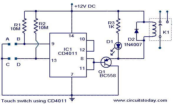
A simple touch switch circuit using the CD4011 is presented. The CD4011 integrated circuit (IC) is configured as a flip-flop. Pins 9 and 13 of the IC function as the set and reset terminals, respectively. CMOS ICs like the...
A TV remote jammer circuit using the NE555 timer IC. This device allows users to watch their favorite TV channels without interruptions, as it prevents others from changing the channel using a remote control when the circuit is activated....
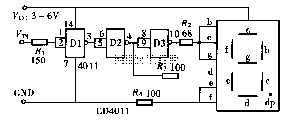
The door circuit logic pen text display can take many forms, utilizing various logic gates such as inverters, NAND gates, NOR gates, and others. A logical pen, exemplified by the NAND gate CD4011, can be used in conjunction with...
A square wave generator with a variable frequency and a 50% duty cycle is required. While the 555 timer is a common choice, the standard astable multivibrator configuration alters the duty cycle when the frequency is adjusted. A circuit...
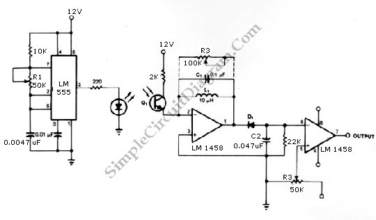
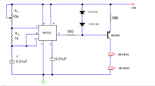
The infrared transmitter and receiver circuit depicted in the schematic diagram can function as a remote control system. The transmitter operates as an oscillator circuit, with the frequency adjustable through the R1 potentiometer (or trimmer pot). This oscillation ensures...
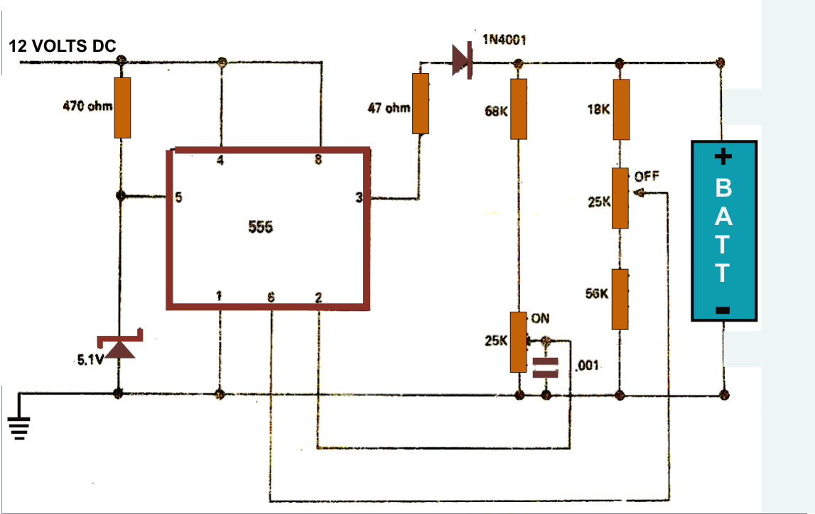
The simple battery charger circuit design presented here utilizes the versatile IC 555 as its primary component. This circuit is capable of charging various types of rechargeable batteries within the specified limits outlined in the article. The battery charger circuit...