
555 Timer as an Analog to Digital Converter

The 555 timer is a versatile integrated circuit commonly used for timing, oscillation, and pulse generation applications. In this configuration, it operates in astable mode to convert varying analog voltages into a series of digital pulses that can be counted or interpreted by a microcontroller or other digital logic devices.
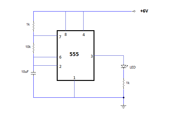
The circuit typically consists of the 555 timer, resistors, capacitors, and a reference voltage source. The analog input voltage is applied to one of the timer's input pins, while a reference voltage is set at another pin to establish a threshold for the conversion process. The timing components (resistors and capacitors) determine the frequency of the output pulses, which correlate to the magnitude of the input voltage.
As the input voltage changes, the output pulse width varies accordingly. This pulse width can then be measured using a digital counter or microcontroller, which translates the width into a corresponding digital value. The resolution of the conversion is dependent on the timing components and the reference voltage used.
In practical applications, this 555 timer-based voltmeter and analog-to-digital converter can be employed in various fields, including automation, instrumentation, and embedded systems, where precise voltage measurements are required. The simplicity of the circuit design and the availability of the 555 timer make it an attractive option for engineers and hobbyists alike.This 555 timer based circuit is a kind of voltmeter, also an analog to digital converter, that converts the analog input voltage to digital output pulses 🔗 External reference
Related Circuits
The NE555 is one of the most commonly used timer integrated circuits (ICs). It is a monolithic timing circuit capable of producing accurate and highly stable time delays or oscillations. Similar to general-purpose operational amplifiers, it is reliable, easy...
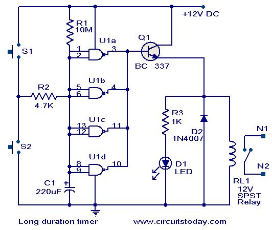
This timer circuit is designed to turn off a specific device after approximately 35 minutes. It can be utilized to switch off appliances such as radios, TVs, fans, and pumps after a predetermined duration of 35 minutes, contributing to...
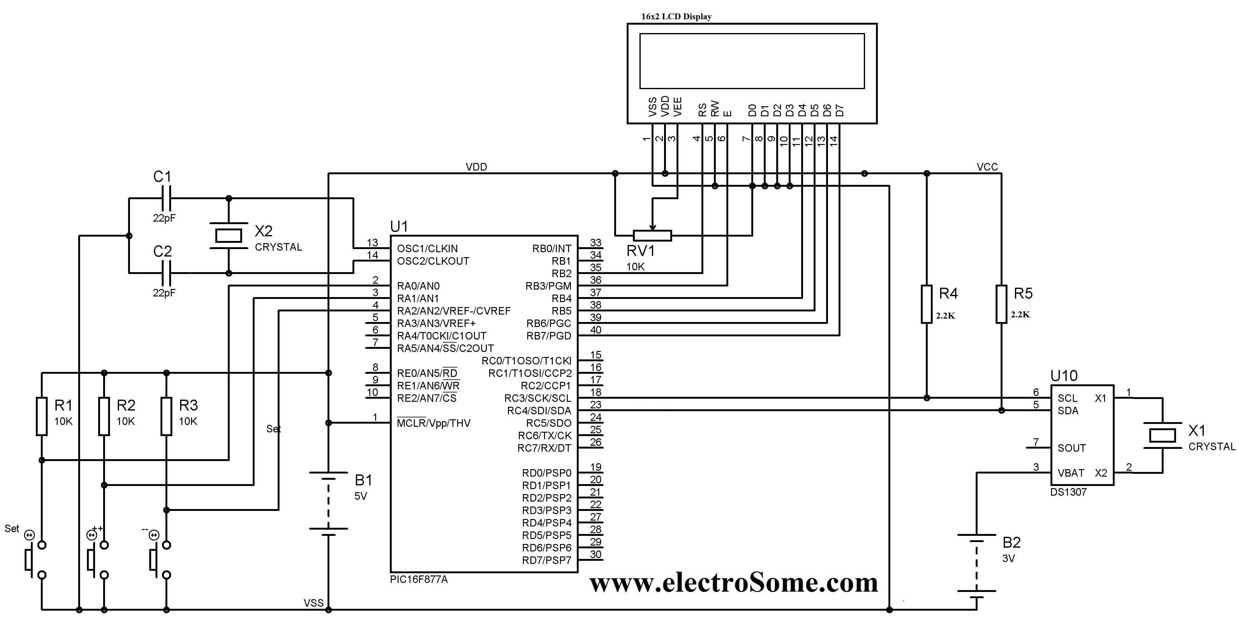
A digital clock can be constructed using a PIC microcontroller, DS1307 real-time clock (RTC), and a 16x2 LCD display. The DS1307 RTC operates in either 24-hour or 12-hour mode with an AM/PM indicator. It adjusts automatically for months with...
The Car Voltage Gauge is based on 3 parts. The input circuit is an Analog to Digital Converter (IC2 CA3162E). The purpose of this chip is to sample an analog voltage and convert it to a decimal value which...
A relay (RL1) is activated with a 100-second delay when a +12V power supply is connected to the circuit. Figure 2 illustrates a relay timer circuit utilizing a 555 timer, featuring two time ranges: 6-60 seconds and 1-10 minutes...
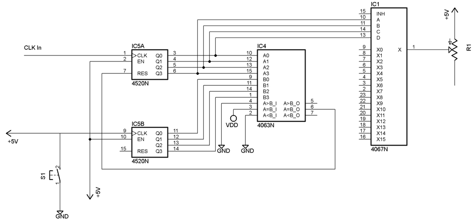
The following video showcases a test circuit of a 16-step analog sequencer based on Mauno Tuominen's schematic for an analog CMOS sequencer utilizing a 4067N multiplexer/demultiplexer. A DIY version of the sequencer can be found at studiomanus.com. An old...