
Amplitude Modulation Receiver Circuit

The amplitude modulation (AM) circuit is engineered to effectively capture and process radio frequency signals. The design focuses on achieving high sensitivity, allowing for the detection of weak signals, and good selectivity, which enables the circuit to distinguish between closely spaced frequencies.
The circuit typically includes several key components: an antenna, a radio frequency (RF) amplifier, a demodulator, and an audio output stage. The antenna is responsible for receiving the incoming AM signals, which are then amplified by the RF amplifier to improve the signal strength.
Following amplification, the demodulator extracts the audio signal from the modulated carrier wave. This process involves mixing the incoming AM signal with a local oscillator signal to produce an intermediate frequency (IF) that can be more easily processed. The demodulated audio signal is then filtered to remove any residual carrier frequency and noise, ensuring that only the desired audio information is passed on.
Finally, the audio output stage converts the demodulated signal into a format suitable for driving speakers or headphones. This may involve further amplification to ensure the audio signal is loud enough for listening. The overall design emphasizes stability and performance, making it suitable for various applications in communication systems where AM signals are prevalent.
In summary, this amplitude modulation circuit is a robust solution for receiving and processing AM signals, offering a balance of sensitivity and selectivity that meets the demands of modern communication needs.The circuit was designed to be able to obtain signals via amplitude modulation where the sensitivity and selectivity is fairly good. Amplitude Modulation.. 🔗 External reference
Related Circuits

The VU meter is categorized into two types: those that use needle instruments and those that employ LED columns. A VU meter sound level meter is essential for both tube amplifiers and integrated amplifiers. Currently, there are numerous integrated...
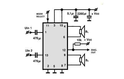
A simple Class B power amplifier can be constructed using the TDA8560 audio integrated circuit (IC). The TDA8560 amplifier features an internally fixed voltage gain, ensuring excellent channel balance. This audio amplifier project is capable of delivering dual 40-watt...

The SOS Alarm centralized control circuit is designed for use in calling a hospital bed and can also serve as an anti-theft alarm in multi-storey buildings, dormitories, warehouses, and similar locations. The circuit, as depicted in Figure 13-64, features...
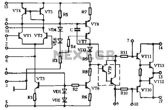
A preferred STK4040xl Fi amplifier circuit exhibits excellent electrical parameters: under specific conditions, the output voltage (Uc) is 43V with a load resistance (RL) of 8 ohms. The circuit is designed to deliver a rated output power of at...
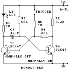
An oscillator is a mechanical or electronic device that operates based on the principles of oscillation. Oscillators serve as fundamental building blocks upon which the entire structure of electronics and computers is established. An article is available that explains...
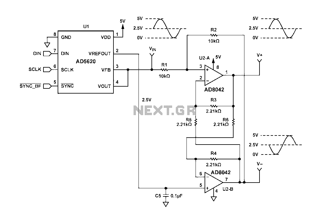
Figure 1 illustrates a circuit that utilizes a single +V power supply and a voltage output Digital-to-Analog Converter (DAC) known as the AD5620. The DAC is controlled via an SPI port, with its output ranging from 0 V to...