
555 meter circuit diagram of a DC voltage

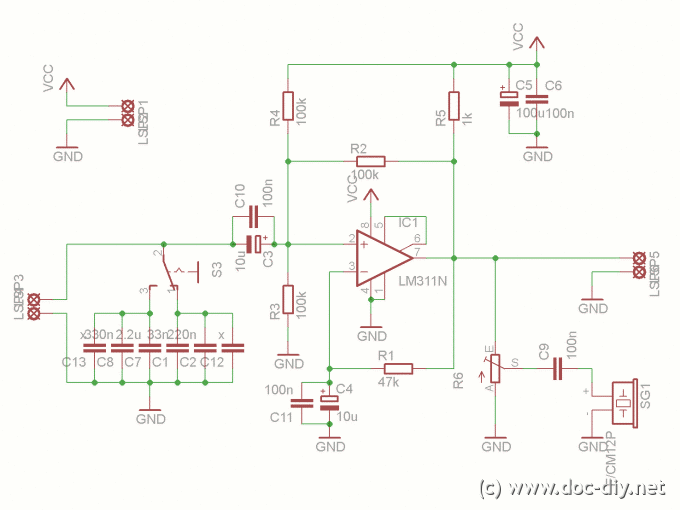
The described circuit utilizes a 555 timer integrated circuit configured in a comparator mode to detect and compare input voltage levels. The control terminal (5 feet) is connected to a reference voltage, while the threshold terminal (6 feet) receives the input voltage to be measured. The internal comparators of the 555 timer will trigger an output when the voltage at the threshold terminal exceeds the reference voltage by a small margin, specifically 5 mV.
When a DC voltage is applied across the designated terminals, the circuit is designed to illuminate LED1 when the input voltage is above the reference level and LED2 when it is below. This visual indication provides immediate feedback on the voltage level being measured.
The resistance value of RP1 can be adjusted to modify the sensitivity of the measurement. As the resistance changes, the range of voltage that can be effectively measured is altered, allowing for a versatile application across different voltage levels. The alternation of the two LEDs serves as an indicator of the current measurement range, with the specific range being determined by the setting of RP1.
The voltage measurement ranges are clearly defined as follows: 0-1V for low voltage applications, 0-10V for moderate voltage scenarios, 0-100V for higher voltage measurements, and 0-1000V for very high voltage applications. This multi-range capability makes the circuit suitable for various electronic testing and monitoring tasks, ensuring that it can accommodate a wide spectrum of voltage levels while providing reliable and accurate readings. As shown, the control terminal 5 feet and 555 threshold end 6 feet is actually two internal input voltage comparator I, as long as 6 feet voltage is higher than 5 feet 5mV, the n 555 will reliably trigger. Applying a DC voltage to the figure of + - terminal, if the voltage is high, LED1 light; low voltage, LED2 light. Change the range and RP1, when the two alternately flashing arc tube, the range is multiplied by RP1 indicators, is the measured voltage V number.
Fourth gear measuring range: 0-1V, 0-10V, 0-100V, 0-1000V.
Related Circuits
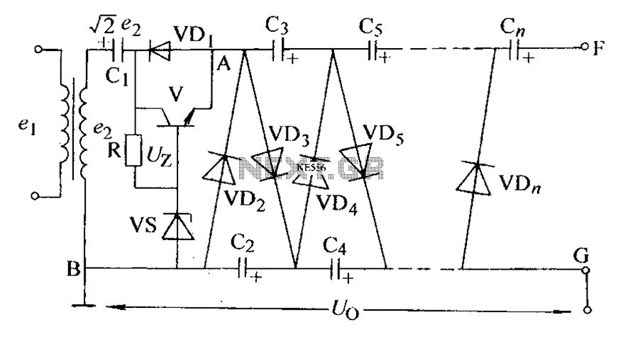
The circuit is an adjustable output voltage regulator type rectifier. It allows for obtaining peak voltage at odd multiples when the output voltage is taken from the circuit feedback (FB). Additionally, the lower point of the capacitor (CB) can...
The use of a quarter-wave parallel-wire line as a tuning unit has been discussed in the chapter on Short-Lines, where it was pointed out that these circuits have comparatively high Q even at higher frequencies. Their significant length (approximately...
There are instances where a 5-V supply voltage is available, but certain components within the circuit require a lower voltage supply. In such cases, a voltage regulator from the Texas Instruments TPS62000 family is an excellent solution, particularly when...
This article explains the process of constructing a basic inductance meter. The printed circuit board (PCB) layout is provided. The construction of a simple inductance meter involves several key components and a well-designed PCB layout to ensure accurate measurements of...
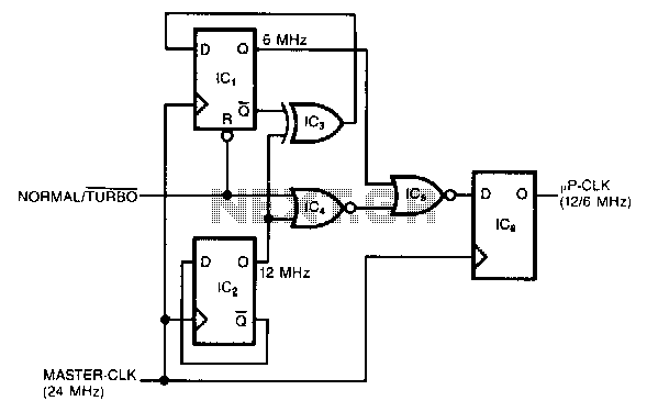
This circuit generates a dual-speed clock for personal computers. It synchronizes asynchronous switch inputs with the master clock to provide glitch-free transitions between clock speeds. The dual-speed clock allows certain programs to operate at a higher clock speed for...
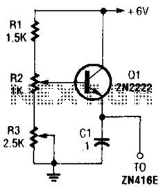
This regulator can be used with a +6-V source to supply the ZN416E low-voltage TRF radio receiver IC with the necessary +1.5 V. R3 sets the output voltage. The circuit utilizes a voltage regulator designed to convert a +6 V...