
+1.5V Supply For Zn416E circuits

The circuit utilizes a voltage regulator designed to convert a +6 V input into a stable +1.5 V output, specifically tailored for powering the ZN416E low-voltage TRF radio receiver integrated circuit (IC). The regulator's primary function is to ensure that the ZN416E receives a consistent voltage level, which is crucial for its operation and performance in radio frequency applications.
In this configuration, R3 plays a pivotal role in determining the output voltage level. By adjusting the resistance value of R3, the output voltage can be fine-tuned to achieve the desired +1.5 V. This is typically done by using a voltage divider approach or feedback mechanism that allows for precise control over the output. The selection of R3 should be made considering the desired output voltage and the characteristics of the voltage regulator being used.
The input voltage of +6 V is connected to the input terminal of the voltage regulator, which then regulates the voltage down to +1.5 V at the output terminal. It is essential to ensure that the input voltage remains within the specified range for the regulator to function correctly and maintain the output voltage stability. Additionally, proper bypass capacitors should be placed at the input and output terminals of the regulator to filter any high-frequency noise and provide transient response stability.
Overall, this voltage regulation setup is critical for the reliable operation of the ZN416E, enabling it to perform effectively in low-voltage applications such as TRF radio receivers. This regulator can be used with a +6-V source to supply ZN416E low-voltage TRF radio-receiver IC the necessary +1.5 V. R3 sets output voltage.
Related Circuits
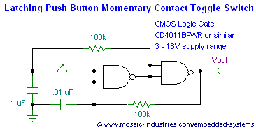
This page presents soft power switch circuits designed for toggling electronic devices ON and OFF with a momentary button press that controls a latching high-side MOSFET power switch. Multiple micropower latching switch circuits are included. Due to their low...
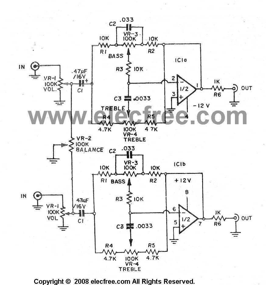
A high-quality preamplifier with tone controls consisting of three circuits. The NE5532 is chosen as the main integrated circuit due to its ultra-low noise properties, making it a popular choice in fine audio applications. Although these circuits are older...
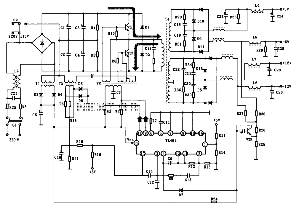
The BE-150 mainframe computer features a switching power supply circuit. The circuit utilizes the oscillation control IC TIA94. A 22V voltage is supplied through the power switch S1, fuse, filter capacitor C21, L2, and a mutual inductance filter, which...
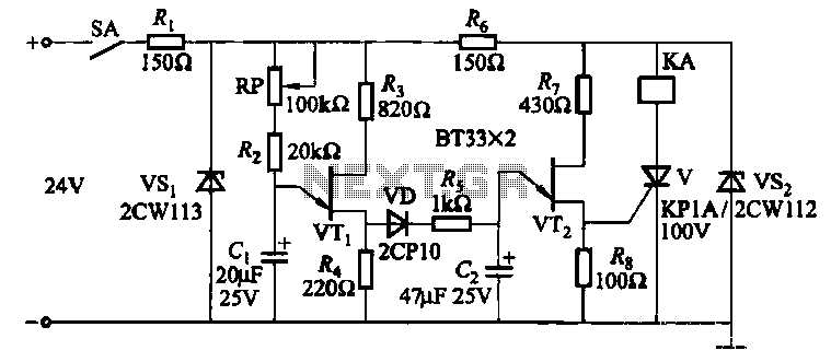
This circuit consists of three single-junction transistor time relay circuits utilizing a pulse charging mechanism, allowing for extended delay times of up to several minutes. The first stage delay circuit incorporates unijunction transistors (VTi) and other components, where capacitor...
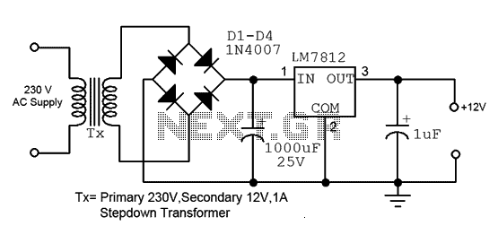
This is a straightforward 12V power supply circuit diagram. It features a fixed voltage output and is based on the LM7812 voltage regulator integrated circuit. The 12V power supply circuit utilizing the LM7812 voltage regulator is designed to provide a...
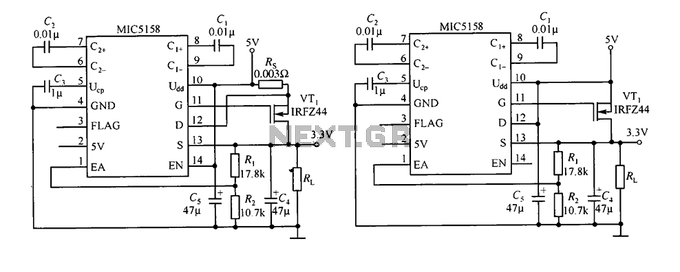
The circuit consists of peripheral components for the MIC5158, a linear regulator that converts a 5V input into a 3.3V output with a maximum current of 10A. When the input voltage (Ui) is 5V, an N-channel MOSFET, specifically the...