
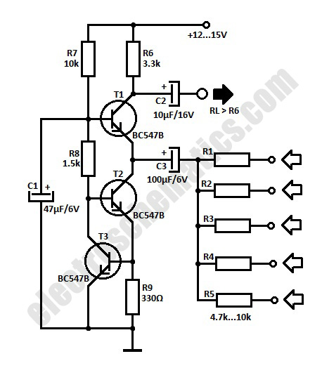
Simple servo controller Schematic

The described circuit for testing a servo motor primarily utilizes a 10k potentiometer, which serves as a variable resistor to control the angle of the servo. The circuit typically includes a power supply, a microcontroller or a servo driver, the servo motor itself, and the potentiometer. The potentiometer is connected to an analog input of the microcontroller, allowing the user to adjust the voltage level based on the position of the potentiometer.
The microcontroller reads the voltage from the potentiometer and translates it into a corresponding angle for the servo motor. The servo motor is designed to move to a specific position based on the input signal it receives, which is often a Pulse Width Modulation (PWM) signal. The width of the pulse determines the angle to which the servo will turn.
In cases where the servo does not reach the desired positions, it may be necessary to modify the resistance values in the circuit. This can be achieved by replacing the 10k potentiometer with one of a different value or by adding additional resistors in series or parallel to fine-tune the voltage range sent to the microcontroller. Adjusting the resistor values may help accommodate different types of servos or specific application requirements.
In summary, this circuit is a practical tool for testing servo motors, allowing for precise control over their angle of movement through the use of a potentiometer. However, users should be prepared to experiment with different resistor configurations to optimize performance for various types of servos.This cicuit allows you to test a servo. The angle of the servo can be set by means of the 10k potmeter. Perhaps you will not be able to reach all positions with this circuit. Playing with other resistors may help. 🔗 External reference
Related Circuits
The Controller Area Network (CAN) data rate ranges from 10 kbit/s to 1 Mbit/s, with recommended distances of 40 to 1000 meters using two twisted pairs—one for data and the other for power and ground. Up to 110 nodes...
A low-cost continuous wave (CW) superheterodyne receiver operates with a 4.00 MHz intermediate frequency. While there is no automatic gain control (AGC) or RF gain control, the receiver demonstrates good large signal handling capabilities. The design incorporates six bipolar...
Most PN-junction diodes can be utilized as photodiodes. Although they are not specifically optimized for this purpose, they are functional. When reverse biased, a diode generates a small photovoltaic output that increases with light intensity. Light Emitting Diodes (LEDs)...
This is a simple servo tester which will comprehensively test the capabilities of almost any modern servo. It has two pushbuttons, CENTRE and SWEEP and a potentiometer which works as follows: CENTRE Does exactly that, centers the servo, afterwards...
The simple audio mixer circuit is built on the common base principle, where input voltages are transformed into alternating currents which are summed to form the output. The simple audio mixer circuit utilizes a common base configuration to achieve effective...
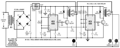
This is a simple traffic light controller that can be used to teach children the basics of traffic light rules. The circuit employs commonly available electronic components and consists of rectifier diodes (1N4001), a 5V regulator (7805), two timer...