
555 meter frequency meter schematic

The 555 timer in monostable mode is designed to produce a single output pulse of a specified duration in response to an external trigger signal. In this configuration, R1 (a resistor) and C1 (a capacitor) determine the timing interval of the output pulse. When the input square wave signal is applied, it is first processed by a Schmitt trigger, which cleans up the signal by providing hysteresis. This ensures that the trigger input is sharply defined, reducing noise susceptibility.
Upon receiving a valid trigger from the Schmitt trigger, the 555 timer activates, causing the output to transition from a low state to a high state. The duration for which the output remains high is determined by the time constant, calculated using the formula T = 1.1 * R1 * C1, where T is the time period in seconds. After this time elapses, the output returns to a low state.
Additional components may include diodes for protection against voltage spikes, and additional resistors or capacitors may be included to further refine the circuit's performance. The monostable delay circuit is widely used in applications such as timers, pulse width modulation, and as a delay mechanism in various electronic systems. The integration of the Schmitt trigger enhances the reliability of the circuit, making it suitable for environments with fluctuating signal levels.FIG. 555 and R1, C1 and other components monostable delay circuit, the input square wave signal or square wave signal by a Schmitt trigger shaping after the trigger requirement s of the circuit 555.
Related Circuits
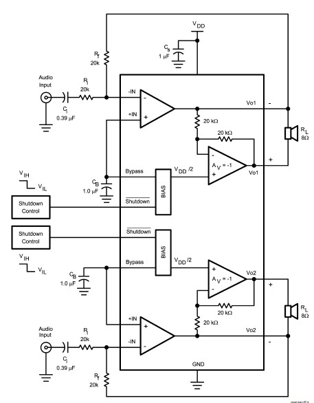
The LM4992 stereo audio power amplifier can be utilized to design a straightforward audio power amplifier project suitable for portable electronic devices. This amplifier circuit is capable of delivering 1 watt of continuous average power per channel to an...

This circuit is a simple LED voltmeter designed to monitor the charge level of lead-acid or tubular batteries. The terminal voltage of the battery is displayed through four LED indicators. The nominal terminal voltage for a fully charged lead-acid...
This circuit is designed for precise centigrade temperature measurement. It includes a transmitter section that converts the sensor's output voltage, which is proportional to the measured temperature, into frequency. The output frequency bursts are transmitted through the mains supply...
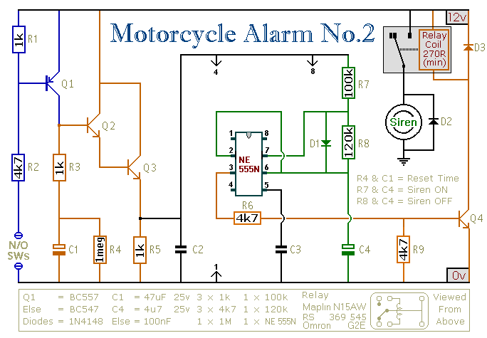
This circuit provides an intermittent siren output with an automatic reset function. It can be manually activated using a key switch or a concealed switch, and it can also be configured to engage automatically when the ignition is turned...
Below is the main schematic of the RX + Xtall V9.0 SDR. The schematic has been divided into separate stages, each covered in its own page of build instructions on this website. Each shaded area can be clicked to...
The circuit is designed to enable rapid changes in motor speed and direction by utilizing four outputs to drive a MOSFET H-bridge. The lower rail power MOSFETs are N-channel devices, while the upper rail MOSFETs are P-channel. All MOSFETs...