
555 Oscillator Tutorial (Astable Multivibrator)
")
The 555 timer IC is a versatile and widely used component in electronics, particularly for generating precise timing and waveform generation. The astable mode of the 555 timer allows it to function as an oscillator, producing continuous square wave signals without the need for external triggering.
In an astable configuration, the 555 timer operates between two unstable states, continuously switching between them. The circuit typically consists of two resistors (R1 and R2) and a capacitor (C1) connected to the 555 timer. The resistors determine the charge and discharge times of the capacitor, which in turn dictate the frequency and duty cycle of the output waveform.
The output frequency (f) of the square wave can be calculated using the formula:
\[ f = \frac{1.44}{(R1 + 2R2) \times C1} \]
Where:
- R1 is the resistor connected between Vcc and the discharge pin (pin 7).
- R2 is the resistor connected between the discharge pin and the threshold pin (pin 6).
- C1 is the capacitor connected between the threshold pin and ground.
The duty cycle percentage, which indicates the proportion of time the output is high versus low, can be calculated with the formula:
\[ Duty Cycle = \frac{R2}{R1 + 2R2} \times 100 \]
The output frequency and duty cycle can be adjusted by varying the values of R1, R2, and C1, allowing for a wide range of applications. The output of the 555 timer in astable mode can be used to drive LEDs, create clock pulses for digital circuits, or generate audio tones.
To implement the circuit, the 555 timer should be connected as follows:
- Connect pin 1 (GND) to ground.
- Connect pin 2 (Trigger) to pin 6 (Threshold).
- Connect pin 3 (Output) to the desired load or output device.
- Connect pin 4 (Reset) to Vcc to disable the reset function.
- Connect pin 5 (Control Voltage) to ground through a capacitor (typically 0.01 µF) for stability.
- Connect pin 6 (Threshold) to pin 2 (Trigger) and to R2.
- Connect pin 7 (Discharge) to R1 and to C1.
- Connect pin 8 (Vcc) to the positive supply voltage.
By carefully selecting the resistor and capacitor values, the 555 astable oscillator can be tailored to meet specific frequency and duty cycle requirements for various electronic applications.Electronics Tutorial about the 555 Oscillator and How the 555 Oscillator can be used as a 555 Astable Oscillator Circuit to Generate Square Wave Waveforms.. 🔗 External reference
Related Circuits

QST's latest development, the Tri-tet oscillator, has finally made the single-tube crystal transmitter a practical option. It is now feasible to operate effectively on two, and occasionally three, amateur bands using a single crystal. This particular device signifies the...
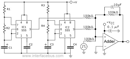
This circuit combines the outputs from two distinct 555 multivibrators using a summing operational amplifier (Op Amp). It serves to illustrate an alternative implementation of a 555 timer, with most background calculations addressed in other sections. The standard configuration...
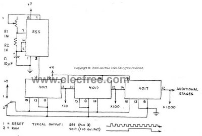
This circuit is designed to provide long time delays using the integrated circuit Timer 555. It utilizes the NE555 to generate pulse frequencies, which are then divided by a 4017 decade counter to achieve the desired delay. The component...
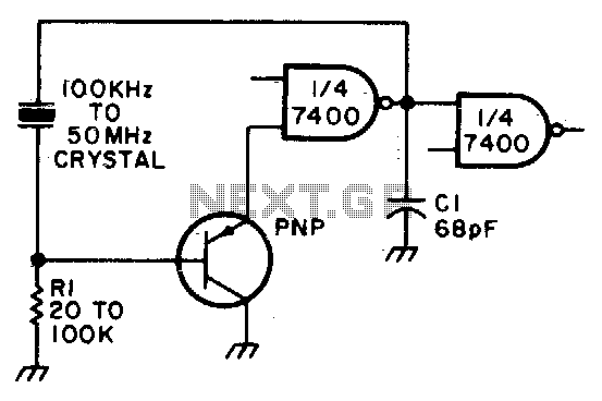
Adjust Rl for approximately 2 volts at the output of the first gate. Additionally, adjust Cl for optimal output. In the context of electronic circuit design, the output voltage of a gate, such as a logic gate or operational amplifier,...
This is an astable multivibrator (oscillator) circuit using a CMOS inverter. The circuit employs the CD4007 or MC14007 integrated circuit. The operating frequency range of this circuit is not specified. The astable multivibrator circuit utilizes CMOS technology to create a...
The circuit presented is a standard Colpitts oscillator, commonly utilized in many amateur radio homebrew transmitters. This specific circuit is designed to operate effectively within a frequency range of 1500 kHz to 8000 kHz. To accommodate lower frequencies, it...