
555 precision temperature sensor with temperature frequency converting circuit diagram

The 555 precision temperature sensor operates by converting temperature variations into frequency signals. This circuit typically utilizes a 555 timer IC configured in astable mode to generate a pulse-width modulation (PWM) signal whose frequency is directly proportional to the temperature being measured.
In this configuration, the temperature sensor (often a thermistor or an integrated temperature sensing component) is connected to the input of the 555 timer. As the temperature changes, the resistance of the sensor alters, which in turn modifies the charge and discharge times of the timing capacitor connected to the 555 timer. This results in a frequency output that varies with temperature.
The circuit may include additional components such as resistors and capacitors to fine-tune the frequency response and to stabilize the operation of the 555 timer. The output frequency can be measured using a frequency counter or microcontroller, allowing for precise temperature monitoring and control applications.
This design is particularly useful in applications that require temperature measurement in real-time, such as in HVAC systems, environmental monitoring, and industrial processes where temperature regulation is critical. The simplicity and reliability of the 555 timer make it an excellent choice for integrating temperature sensing capabilities into various electronic systems.555 precision temperature sensor with temperature frequency converting circuit diagram consisting of:
Related Circuits
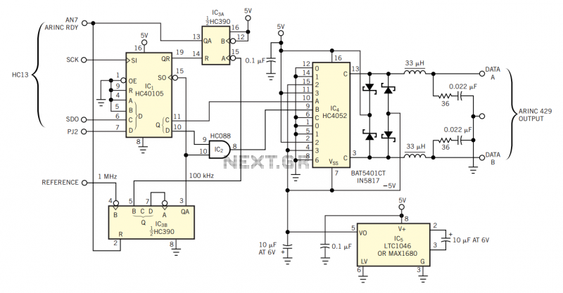
The physical transmission medium for the 429 standard is 78Ω shielded, twisted-pair cable that uses a complementary, differential bipolar RZ (return-to-zero) waveform. The voltages are the net differentials that the biphase drive develops: For example, the differential is 10V...
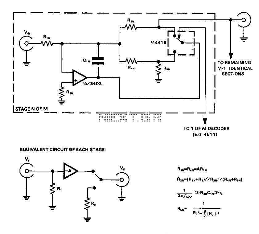
CMOS switches are utilized to select entries in audio circuits. While these switches can introduce unacceptable levels of distortion, incorporating them into the feedback network of an operational amplifier (op amp) can effectively minimize this distortion. The circuit employs...
The cumulative timer circuit comprises resistor R1 and an internal crystal oscillator, represented in a chart. Resistors R1 and R2 are metal film types, while resistors R3 to R5 are rated at 1/8W and also of the metal film...
When the circuit is connected to hi-fi equipment or at both ends of the electronic instrument's speaker, the audio level can be modulated to a 500W lamp proportionally. This is achieved using three appropriate sets of audio filters and...
The Adjustable Timer circuit initiates timing upon activation. A green LED illuminates to indicate that timing is in progress. Once the designated time period elapses, the green LED turns off, the red LED activates, and an audible bleeper sounds....
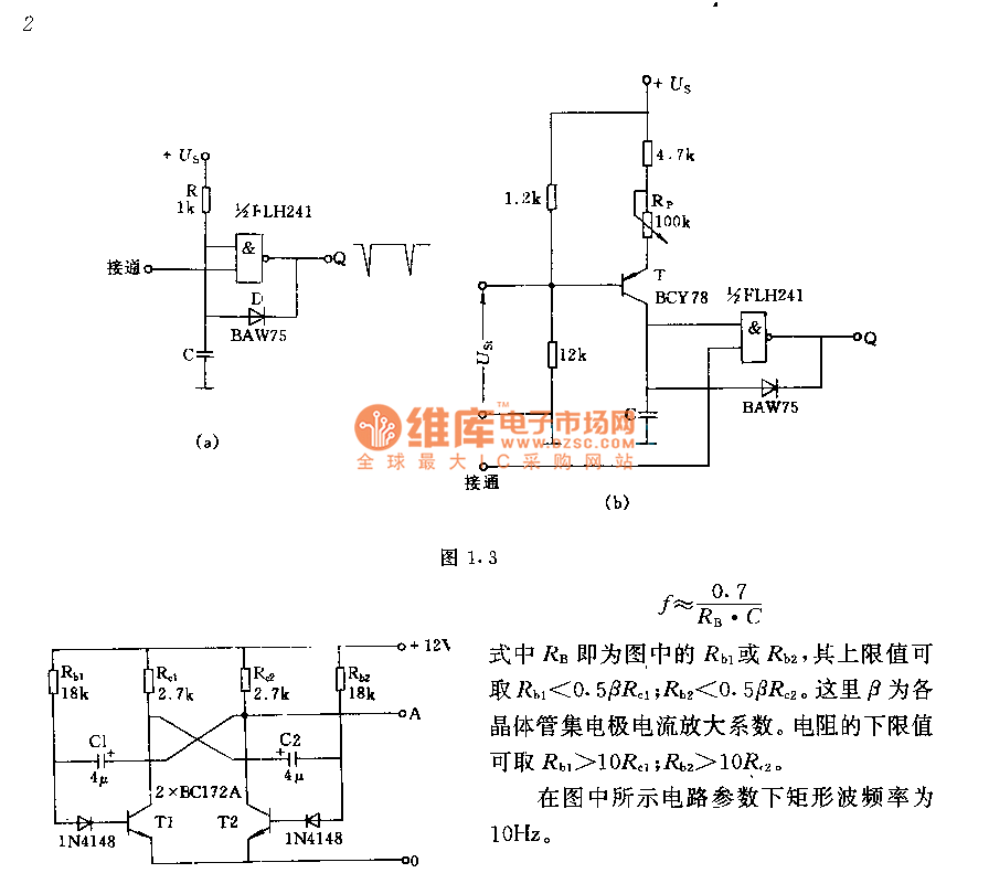
The circuit consists of two components whose parameters and models are designed to simultaneously generate a rectangular wave with a duty cycle of 1:1. The frequency is defined by the equation f = 0.7/(RB * C), where RB refers...