
555 Timer as an A/D converter

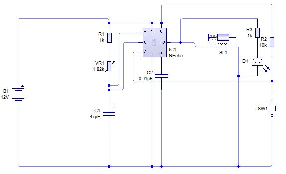
The described circuit employs a 555 timer configured in astable mode to generate a series of pulses that can be used to measure the voltage of a battery, specifically targeting a nominal 12-volt source. The key operation involves using a capacitor with a specified capacitance of 4.7 µF, which is charged and discharged based on the input voltage at the "ANALOG IN" pin. The output pulse width from the 555 timer is influenced by the voltage level at this input, allowing for a direct correlation between the pulse width and the measured voltage.
To construct the circuit, the following components are required: a 555 timer IC, a 4.7 µF capacitor, resistors for setting the timing characteristics, and a Basic Stamp microcontroller for reading the output pulses. The resistors will be selected to set the frequency of oscillation of the 555 timer, ensuring that the output pulses can be accurately measured by the Basic Stamp.
Calibration of the circuit is essential for accurate voltage measurement. This is achieved by applying a known voltage to the "ANALOG IN" pin and adjusting the resistor values accordingly to ensure the pulse width corresponds correctly to the applied voltage. The Basic Stamp will count the number of pulses over a fixed time interval, allowing for the calculation of the input voltage based on the known relationship between pulse width and voltage difference.
This approach provides a straightforward and effective means of measuring battery voltage, making it suitable for various applications where monitoring battery status is critical. The use of a 555 timer in this context illustrates its versatility beyond simple timing applications, showcasing its capability in analog voltage measurement tasks.I had a Basic Stamp project that needed to measure a nominal 12 volt battery, and I wanted a simple solution. This is the simplest I could come up with. The 555 timer will put out positive pulses. The pulse width is inversely proportional to the difference in voltage between the voltage at "ANALOG IN" and the voltage of the 4.7uF capacitor(let`s say 2.5 volts).
To calibrate this circuit, hook it up to a Basic Stamp measuring positive pulses, and give the circuit a known voltage. 🔗 External reference
Related Circuits
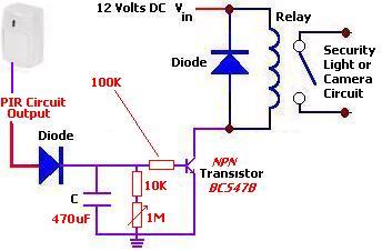
The following circuit illustrates a PIR Sensor Timer Circuit Diagram. Features include a simple design, enhanced accuracy, and efficiency. Components involved are a diode, among others. The PIR (Passive Infrared) Sensor Timer Circuit is designed to detect motion through infrared...
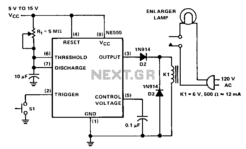
The NE555 circuit functions as a basic one-shot timer, featuring a relay connected between the output and ground. It is triggered by a normally open momentary contact switch, which, when activated, grounds the trigger input at pin 2. This...
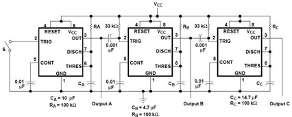
A sequential timer circuit device is utilized in various applications for initializing conditions during start-up or for activating test signals in sequences, such as in test equipment devices. The circuit diagram below illustrates a sequencer circuit with potential applications...
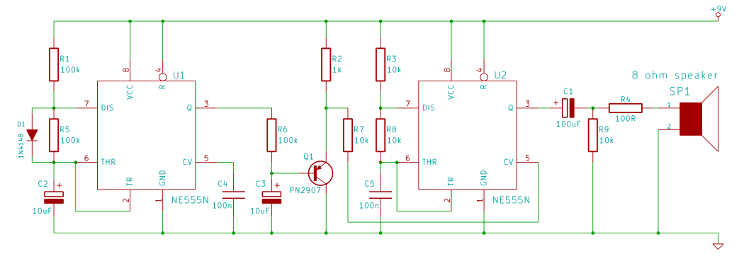
This tutorial outlines the construction of a wailing siren that produces a tone with varying pitch. The circuit incorporates two 555 integrated circuits (ICs) and a loudspeaker. The wailing siren circuit is designed to create an audio effect that simulates...
A thermistor is utilized in the circuit for heat sensing, while two 5K variable resistors are incorporated to calibrate the circuit for activating the relay at the desired temperature. The inclusion of a 1N4007 diode across the relay serves...
A circuit is being designed to trigger solenoid valves for airbags in a car, requiring a time range of 0 to 1 second. The selected valves operate at 12V, 0.5A, and can activate within a maximum speed of 200...