
PIR Sensor Timer

The PIR (Passive Infrared) Sensor Timer Circuit is designed to detect motion through infrared radiation emitted by objects in its field of view, typically human bodies. This circuit is particularly useful in security systems, automatic lighting, and energy-saving applications.
The core of the circuit is the PIR sensor, which generates a low-level output signal when it detects motion. This signal is then processed by a microcontroller or a timer circuit that can control the duration of the output signal, thus activating connected devices such as lights or alarms.
The components of the circuit typically include:
1. **PIR Sensor**: This component detects infrared radiation changes and produces a digital output when motion is sensed. The sensor usually has two outputs: one for detection and another for triggering.
2. **Diode**: Used for rectification and protection purposes, ensuring that current flows in the correct direction and safeguarding the circuit from voltage spikes.
3. **Resistors**: Employed to limit the current and set the sensitivity of the PIR sensor. They can also be used in voltage divider configurations to adjust signal levels.
4. **Capacitors**: Used for filtering and stabilizing the power supply to the PIR sensor, as well as for timing applications in conjunction with other components.
5. **Microcontroller or Timer IC**: This component processes the signal from the PIR sensor and controls the output duration. It can be programmed to set how long the output remains active after motion is detected.
6. **Relay or Transistor**: Acts as a switch to control larger loads such as lights or alarms based on the output signal from the timer or microcontroller.
7. **Power Supply**: Provides the necessary voltage and current for the circuit operation, typically sourced from batteries or an AC adapter.
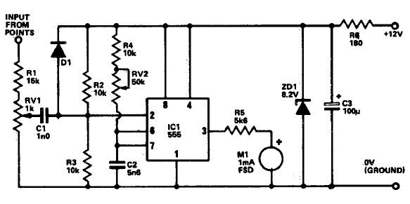
The design of the circuit allows for flexibility in its application, enabling users to adjust parameters such as sensitivity and timing to suit specific requirements. Overall, the PIR Sensor Timer Circuit exemplifies an efficient and straightforward solution for automatic motion detection and control.The following circuit shows about PIR Sensor Timer Circuit Diagram. Features: simple circuit, more accurately, efficient. Component: Diode, .. 🔗 External reference
Related Circuits
The AD537 is a monolithic voltage-to-frequency (V-F) converter that includes an input amplifier, a precision oscillator system, an accurate internal reference generator, and a high-current output stage. A single external resistor-capacitor (RC) network is sufficient to configure any full-scale...
The following circuit illustrates photovoltaic light sensors in a solar tracker. Features include accuracy, low cost, simplicity, and a single-axis electronic design. The photovoltaic light sensor circuit is designed to optimize the alignment of solar panels with respect to the...
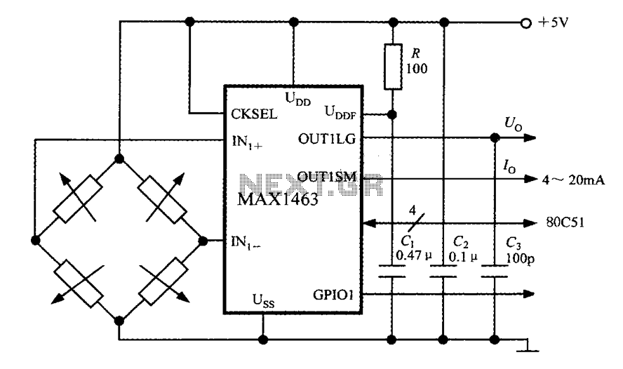
The system consists of a MAX1463 precision pressure detection circuit block diagram. The output voltage from the bridge pressure sensor is connected to the MAX1463 inputs IN1+ and IN1-. Controlled by a CPU, the pressure signal undergoes nonlinear calibration...
The general-purpose circuit of the simple pressure sensor alarm is constructed using a few easily accessible and inexpensive components. The operation of this circuit is straightforward. The simple pressure sensor alarm circuit typically includes a pressure sensor, an operational amplifier...
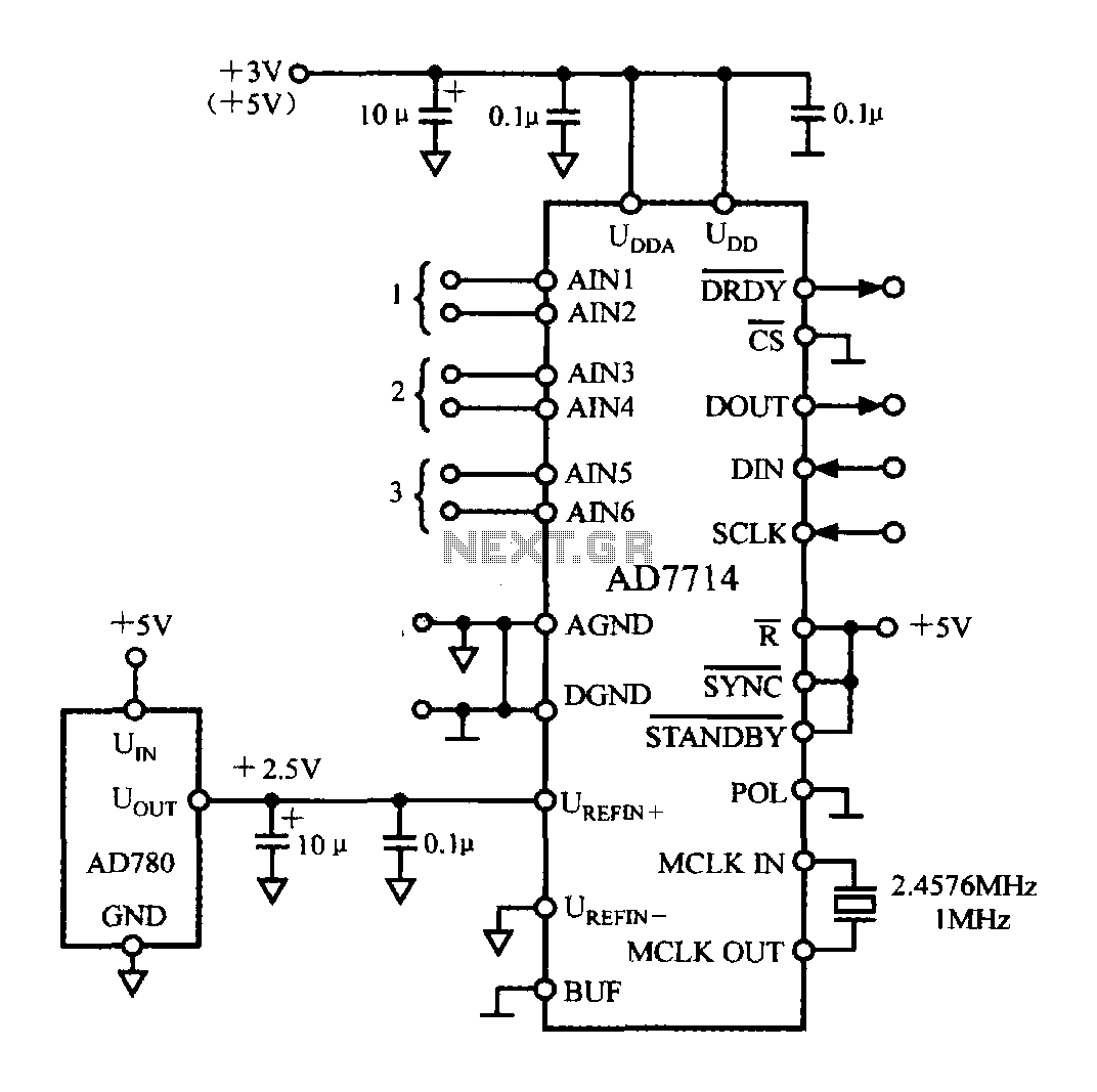
The typical application circuit for the AD7714 is illustrated in the accompanying figure. The UDD and UDDA terminals of the AD7714 can be connected to either a +3V or +5V power supply. The analog inputs are arranged as three...
The following circuit illustrates a Tachometer Circuit Project. This circuit is constructed using the 555 Timer IC. Features include a monostable IC and voltage capabilities. The Tachometer Circuit utilizes a 555 Timer configured in monostable mode to measure the rotational...