
555 Timer as Monostable Multivibrator
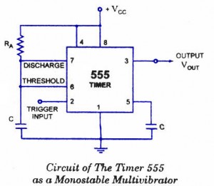
The monostable multivibrator (MMV) circuit utilizing the 555 timer is a highly versatile component in electronic design, particularly for applications requiring precise timing and pulse generation. The configuration of the 555 timer in monostable mode allows for a single output pulse in response to a triggering event, making it suitable for tasks such as time delays, pulse width modulation, and generating clock signals.
In practical applications, the choice of the resistor (RA) and capacitor (C) values is critical, as they directly influence the pulse width of the output signal. The relationship governing the output pulse width (T) is typically expressed as:
\[ T = 1.1 \times RA \times C \]
This equation highlights the linear dependence on both the resistance and capacitance, allowing designers to tailor the timing characteristics to meet specific requirements. The selection of components should consider tolerance, temperature stability, and the frequency response of the circuit to ensure reliable operation under varying conditions.
The robustness of the 555 timer in monostable mode is further enhanced by the addition of bypass capacitors at pin 5, which helps to filter out noise that could inadvertently trigger the output. The careful grounding of pin 1 ensures a stable reference point for the circuit, minimizing the risk of erroneous behavior.
In summary, the monostable multivibrator circuit exemplifies a fundamental electronic building block that can be adapted for a wide range of timing applications, from simple delay circuits to complex pulse generation systems, demonstrating its enduring relevance in modern electronics.A monostable multivibrator (MMV) often called a one-shot multivibrator, is a pulse generator circuit in which the duration of the pulse is determined by the R-C network, connected externally to the 555 timer. In such a vibrator, one state of output is stable while the other is quasi-stable (unstable). For auto-triggering of output from quasi-stable state to stable state energy is stored by an externally connected capaci tor C to a reference level. The time taken in storage determines the pulse width. The transition of output from stable state to quasi-stable state is accom plished by external triggering.
The schematic of a 555 timer in monostable mode of operation is shown in figure. Pin 1 is grounded; pins 4 and 8 are shorted and then tied to supply +Vcc, output (VOUT is taken form pin 3; pin 2 and 6 are shorted and the connected to ground through capacitor C, pin 7 is connected to supply + VCC through a resistor RA; and between pin 6 and 7 a resistor RB is connected. At pin 5 either a bypass capacitor of 0. 01 F is connected or modulation input is applied. Pin 1 is grounded. Trigger input is applied to pin 2. In quiescent condition of output this input is kept at + VCC. To obtain transition of output from stable state to quasi-stable state, a negative-going pulse of narrow width (a width smaller than expected pulse width of output waveform) and amplitude of greater than + 2/3 VCC is applied to pin 2.
Output is taken from pin 3. Pin 4 is usually connected to + VCC to avoid accidental reset. Pin 5 is grounded through a 0. 01 u F capacitor to avoid noise problem. Pin 6 (threshold) is shorted to pin 7. A resistor RA is connected between pins 6 and 8. At pins 7 a discharge capacitor is connected while pin 8 is connected to supply VCC. Initially, when the output at pin 3 is low i. e. the circuit is in a stable state, the transistor is on and capacitor- C is shortedto ground. When a negative pulse is applied to pin 2, the trigger input falls below +1/3 VCC, the output of comparator goes high which resets the flip-flop and consequently the transistor turns off and the output at pin 3 goes high. This is the transition of the output from stable to quasi-stable state, as shown in figure. As the discharge transistor is cut off, the capacitor C begins charging toward +VCC through resistance RA with a time constant equal to RAC.
When the increasing capacitor voltage becomes slightly greater than +2/3 VCC, the output of comparator 1 goes high, which sets the flip-flop. The transistor goes to saturation, thereby discharging the capacitor C and the output of the timer goes low, as illustrated in figure.
The output of the Monostable Multivibrator remains low until a trigger pulse is again applied. Then the cycle repeats. Trigger input, output voltage and capacitor voltage waveforms are shown in figure. where RA is in ohms and C is in farads. The above relation is derived as below. Voltage across the capacitor at any instant during charging period is given as The pulse width of the circuit may range from micro-seconds to many seconds. This circuit is widely used in industry for many different timing applications. 🔗 External reference
Related Circuits
The first positive pulse from a classic 555-based oscillator is always 1.6 times longer than the subsequent pulses. This discrepancy occurs because, during the initial cycle, capacitor C2 begins charging from 0 V. While this is typically not an...
This project involves a simple light-activated police siren utilizing a light-dependent resistor (LDR) and an NE555 timer. It is advisable to complete some preliminary projects before attempting this one. The NE555 timer, configured in slow astable mode with a...
This circuit features an adjustable output timer capable of re-triggering at regular intervals. The output duration can range from a fraction of a second to over half an hour, and it can be configured to recur at regular intervals...
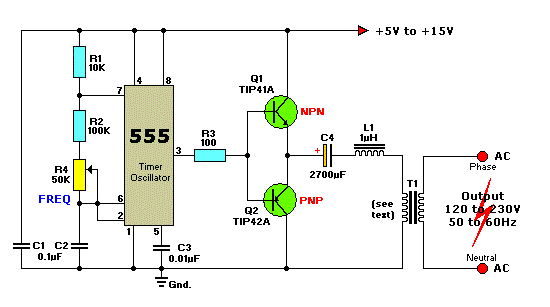
This circuit is a simple 12V DC to 220V AC inverter that produces an AC output at line frequency, specifically 220V AC, or other voltages by selecting transformer T1. The 555 integrated circuit (IC) is configured as a low-frequency...
The capacitor filter operates by measuring the capacitance, which is proportional to the pulse width. This measurement is compared to a nominal capacitance to determine qualification. The circuit, as illustrated in the accompanying figure, includes IC1 along with resistors...
The circuit is composed of a 555 oscillator and an amplifier driver stage. It includes the 555 timer along with resistors R1, R2, RP1, capacitor C1, and other components forming a multi-harmonic oscillator. The frequency can be adjusted using...