
555 Timer Clap Switch

The 555 timer clap switch circuit utilizes a 555 timer IC in a monostable configuration to create a sound-activated switch. The circuit is triggered by a sound, such as a clap, which is detected by a microphone. The microphone converts the sound wave into an electrical signal, which is then amplified and fed into the trigger input of the 555 timer.
Key components of the circuit include a microphone, a preamplifier stage, the 555 timer IC, resistors, capacitors, and a relay. The microphone is typically an electret type, which requires a biasing resistor for proper operation. The amplified signal from the microphone is conditioned using a capacitor to filter out noise and ensure that only significant sound events trigger the timer.
In the monostable mode, the 555 timer produces a single output pulse when triggered. The duration of this pulse is determined by the values of the resistor and capacitor connected to the timer. When the clap sound is detected, the timer activates the relay, which can be used to control a larger load, such as a lamp or other electrical device.
The circuit can be powered by a standard DC power supply, and the output can be adjusted for sensitivity to different sound levels. Additional features may include an LED indicator to show when the circuit is active or a potentiometer to fine-tune the sensitivity of the microphone. Overall, the 555 timer clap switch circuit is a practical application of the 555 timer IC, demonstrating its versatility in sound-activated control systems.This 555 timer clap switch circuit electronic project is designed using some common electronic parts. This 555 timer clap switch circuit electronic projec.. 🔗 External reference
Related Circuits

This time delay switch circuit is designed to activate an AC load, such as lamps, after a delay of three minutes. It helps protect the load from inrush currents and transients during power-on, which can potentially harm the device....
Following the development of the original 4-pin OM802 timer IC by SIGNETICS ITT - GEMINI in 1969/1970, a new and innovative integrated circuit known as the NE-555 timer IC was introduced to the market in May 1971 by Signetics...
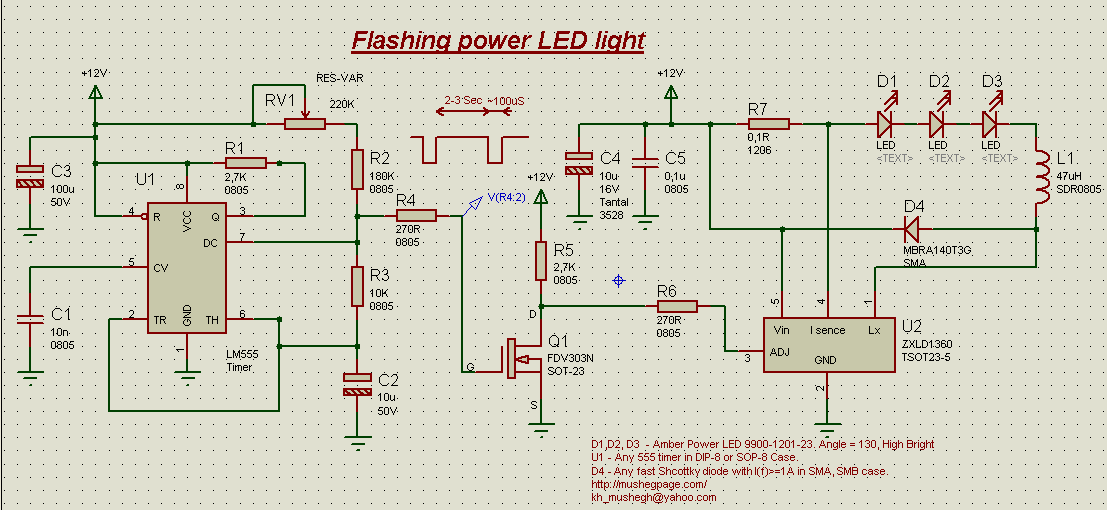
This project demonstrates the construction of a simple flashing light circuit using the IC 555 timer. The 555 timer functions as a clock generator with a duty cycle of less than 100% and greater than 50%. Additional components include...
A collection of drawings showcasing various applications of the 555 timer IC. These include schematic diagrams sourced from online resources and literature, intended for personal reference. The original web pages from which these schematics were derived have not been...
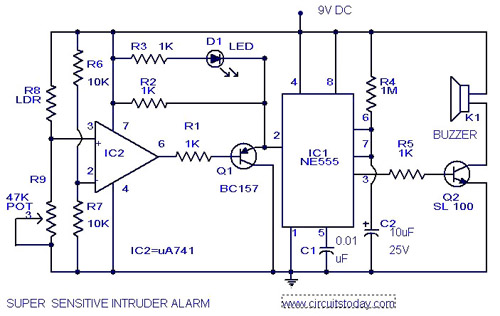
The circuit diagram represents an ultra-sensitive intruder alarm. A shadow from an intruder passing nearby is sufficient to trigger the alarm. The operational amplifier IC2 (uA 741) is configured as a sensitive comparator, with its set point determined by...
This is a programmable clock timer circuit that utilizes individual LEDs to display hours and minutes. Twelve LEDs can be arranged in a circular pattern to represent the 12 hours on a clock face, while an additional 12 LEDs...