Simple Flashing LED Light Based On 555

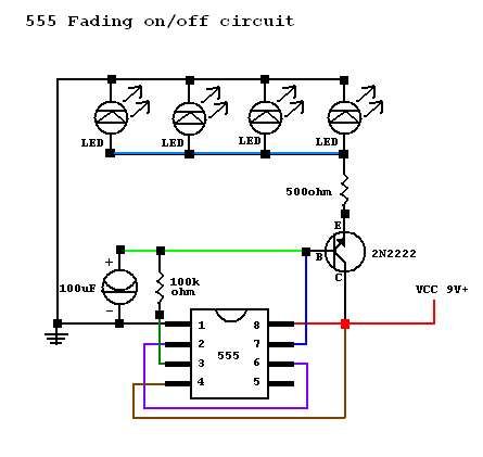
This project demonstrates the construction of a simple flashing light circuit using the IC 555 timer. The 555 timer functions as a clock generator with a duty cycle of less than 100% and greater than 50%. Additional components include a voltage regulator, three amber LEDs, and passive components such as resistors and capacitors.
The circuit utilizes the 555 timer in astable mode, where it continuously oscillates between high and low states, thereby producing a square wave output. This output can be used to drive the amber LEDs, causing them to flash at a frequency determined by the values of the resistors and capacitors in the circuit.
In this configuration, the duty cycle is critical, as it defines the proportion of time the LEDs are on versus off. By selecting appropriate resistor values (R1 and R2) and a timing capacitor (C1), the frequency and duty cycle can be adjusted to achieve the desired flashing effect.
The voltage regulator ensures that the circuit receives a stable power supply, which is essential for consistent LED performance. The LEDs are connected in parallel, allowing them to illuminate simultaneously, while resistors limit the current flowing through each LED to prevent damage.
The passive components, including resistors and capacitors, play a vital role in defining the timing characteristics of the circuit. The capacitor charges and discharges through the resistors, creating the oscillation that drives the flashing effect.
Overall, this project offers an excellent introduction to using the 555 timer for creating visual signals and can be expanded upon by incorporating additional features such as variable flashing rates or integrating it with other electronic components for more complex applications.This project shows you how to build simple flashing light based on IC 555. The 555 has function as clock generator with dutycyle less than 100 and more than 50. The other components are Voltage regulator, 3 power amber LED and passive component like resistor and capacitor.. 🔗 External reference


