
555 / 556 H bridge

The described circuit employs two 555 timer ICs configured as an H-bridge to drive a motor. The primary function of the H-bridge is to allow the motor to rotate in both directions by controlling the polarity of the voltage applied to the motor terminals. The operation begins with the output of the 555 timers, which can be switched between high and low states based on the inputs from the microcontroller. The microcontroller generates PWM signals to modulate the speed of the motor, while the logic signal determines the direction of rotation.
The H-bridge circuit consists of two 555 timer ICs configured as flip-flops, with each timer controlling one side of the H-bridge. The output from the timers is connected to the gates of MOSFETs or bipolar junction transistors (BJTs), which act as switches to connect the motor to the power supply. The motor's terminals are connected to the outputs of the H-bridge, allowing it to receive power in either direction.
The control voltage pin of the 555 timers is crucial for adjusting the threshold levels, allowing the circuit to accommodate different operating voltages. By carefully selecting the resistor values or using a Zener diode, the thresholds can be set to ensure reliable operation with varying supply voltages. This flexibility is particularly beneficial when interfacing with microcontrollers that operate at lower voltages.
The inclusion of an oscilloscope in the testing phase provides valuable insights into the performance of the H-bridge. By observing the output waveforms, one can analyze the effect of different duty cycles on the motor's speed and the influence of the logic signal on the direction of rotation. This feedback is essential for fine-tuning the control parameters and ensuring optimal performance of the motor in various applications.
Overall, this H-bridge design utilizing the 555 timer ICs offers a cost-effective and versatile solution for low-power motor control, suitable for a range of projects requiring bidirectional motor operation and speed modulation.You might find yourself needing a low power H bridge for driving a motor like I once did. The 555 IC can drive a load up to 200mA, source or sink, which might make is usable as a driver, if one can control the output as desired. Although it is an unusual use for a 555/556 IC, it is an easy way to make a bridge with these easy to find and cheap ICs
. They are a good solution for a low power H bridge that operates at a higher voltage than the controlling circuit, up to 15V, requiring only an extra zenner diode. Two comparators control an SR flip flop which drives the output buffer. A high logic level on the Reset input makes the Output go low and a high logic level on the Set pin makes the output go high.
In order to set the output, a voltage lower than 1/3*VCC must be applied to the Trigger pin and in order to reset it a voltage higher than 2/3*VCC must be applied on the Threshold pin. The 1/3 and 2/3 voltage references are given by the three 5K resistors. Connecting the two inputs (threshold and trigger) together means that the output may be set by a voltage under 1/3*Vcc and reset by a voltage over 2/3*VCC.
Two of those circuits together make a H bridge: The 555 offers another advantage: the voltage reference 2/3VCC is connected to the Control voltage pin (see internal block schematic). That means that the two thresholds may be altered by controlling that voltage. If the motor requires a high voltage, such as 12V but needs to be controlled from a lower voltage microcontroller (3.
3 / 5V) the thresholds can be altered by forcing the control voltage pin to another level. Because a voltage higher than the control voltage pin level is required to reset the output, the control voltage pin should be pulled to a level that is some distance below the microcontroller supply. There are two ways to do this: add a resistor between the control voltage pin and ground to form a divider or add a zenner diode to precisely set the voltage.
The former method will work correctly if the supplies are well stabilized, but I prefer the latter. It is well suited even if the higher voltage, the one for the motor, comes from a battery (so it varies in a larger range) and the microcontroller voltage comes from a regulator (so it is stable). Note: I`ve later realized that I could connect the Discharge pin to the output and have a lower drop on the transistor switching to ground, but left the schematic in the original and tested form.
I`m using the microcontroller to generate a 450Hz PWM signal(orange wire) and a logic high/low signal(green wire) with the maximum amplitude of 3. 3V. These control the H bridge. Below are oscilloscope capture images for various duty cycles and directions. The top and bottom signals indicate the outputs, while the middle shows the difference, meaning the actual voltage across the load (which was not present at that moment): Depending on the state of the logic signal(bottom of screen) the output difference is either positive or negative, and has a duty cycle controlled by the PWM signal(top of screen).
This allows controlling the direction of the motor and the speed. I`ve used this microcontroller board for various projects, that`s why it has some other LEDs and connectors. The wire with the connector at the left is the serial port that I am using for programming: The motor used in this project is actually a modified servo motor used for model planes.
I`ve removed the electronics and the mechanical blocking to allow it to spin 360 degrees. The unloaded motor draws about 80mA when connected to a 12V supply. Although I have not seen any visible improvement when tried on this motor, it is possible to connect two (or maybe more ) 556 in parallel and have a higher current capacity, just by putting them one on top of the other. There is another use for this H bridge: if an independent PWM signal is required, one of the 555 ²s from the bridge may be wired in the classical way of a pwm generator.
This creates an H bridge that can control independently vary the speed and direction of a motor. 🔗 External reference
Related Circuits
The first positive pulse from a classic 555-based oscillator is always 1.6 times longer than the subsequent pulses. This discrepancy arises because, during the initial cycle, capacitor C2 begins charging from 0 V. While this is typically not an...
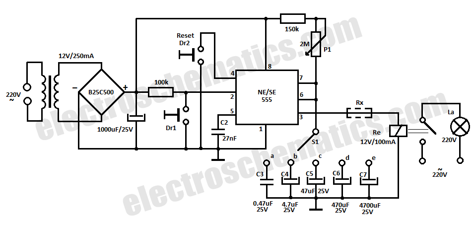
This time delay relay circuit is constructed using the NE/SE555 integrated circuit, manufactured by Intersil, which features a precision timer. The circuit exhibits stability against temperature variations. The NE/SE555 integrated circuit is a versatile timer used in various applications, including...
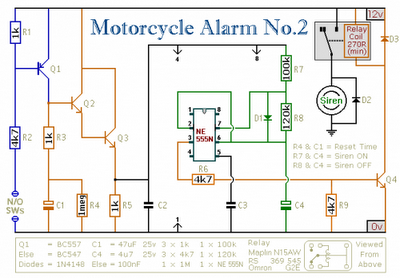
Any number of normally-open switches may be utilized. Install "tilt" switches that close when the steering is moved or when the bike is lifted off its side-stand or pushed forward off its centre-stand. Employ micro-switches to secure removable panels...

The Switchgate is a simple dual gate circuit based on a 556 timer configured in monostable mode, featuring a trigger input that activates two switches. The outputs of the monostables are also available individually. Recent research has led to...
The circuit diagram of a police siren utilizes two NE555 timer integrated circuits (ICs), each configured as an astable multivibrator. It can operate with a power supply ranging from 6 to 15V DC and produces a loud sound. An...
A simple electronic key code lock circuit that requires few external components can be constructed using this schematic diagram. This electronic key code lock circuit is based on a common 555 timer circuit and other standard components. This low-cost...