
555 Timer TV Remote Controlled Home Appliance

The 555 timer integrated circuit (IC) is a versatile component widely used in various electronic applications, including remote control systems for home appliances. In the context of a TV remote-controlled home appliance circuit, the 555 timer is employed to manage the switching operation, ensuring stable and controlled activation of the connected device.
The circuit typically consists of a 555 timer configured in either monostable or astable mode, depending on the desired functionality. In monostable mode, the 555 timer generates a single output pulse when triggered by a signal from the remote control. This output pulse can be utilized to activate a relay or a transistor, which in turn controls the power to the appliance. The duration of the pulse is determined by external resistors and capacitors connected to the timer, allowing for customization based on the specific requirements of the application.
To avoid fast switching, which can lead to erratic behavior or damage to the appliance, the circuit may incorporate additional components such as Schmitt triggers or debounce circuits. These components help to filter out noise and ensure that the activation signal is clean and stable.
The circuit design may also include an infrared (IR) receiver module, which captures signals from the TV remote control. The output from the IR receiver is fed into the trigger input of the 555 timer, enabling the appliance to respond to commands from the remote. The overall circuit can be powered by a standard DC power supply, ensuring compatibility with most home appliances.
In summary, the 555 timer-based remote-controlled appliance circuit is an effective solution for automating home devices, providing a reliable and user-friendly interface for operation through a TV remote control.555 Timer TV Remote Controlled Home Appliance Circuit Diagram. Features: 555 timer IC to avoid fast switching. you can only switch the circuit .. 🔗 External reference
Related Circuits
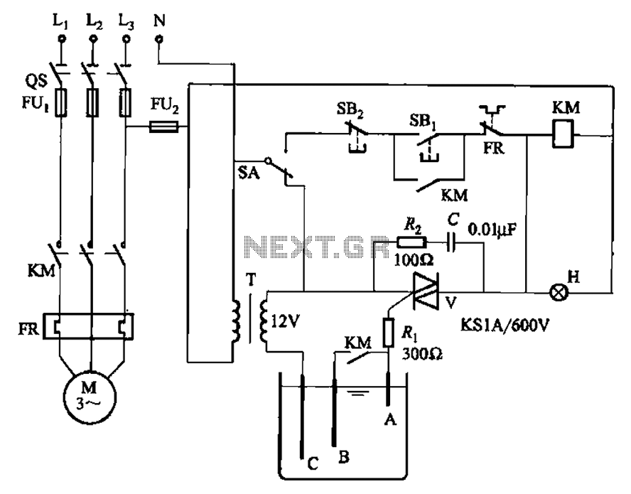
Bidirectional thyristor control manages the trigger voltage output from the step-down transformer at 12V when the water activates the electrodes. It is part of a drawable circuit that regulates the level. The circuit includes a current-limiting resistor (Ri) to...
The remote control transmits encoded signals. Each time a key is pressed, the relevant code is transmitted, usually repeating it many times to ensure reception. This encoded signals travels over a radio or infrared-light beam, to eventually get captured...
The U2745B is a Phase-Locked Loop (PLL) transmitter integrated circuit (IC) designed specifically for low-cost radio frequency (RF) data transmission systems, supporting data rates up to 20 kBaud. It operates within a transmitting frequency range of 310 MHz to...
In this circuit, a 4017 CMOS decade counter can be utilized to construct a timer circuit. The push-button S1 will discharge capacitor C1 through resistor R2. The 4017 CMOS decade counter is a versatile integrated circuit that can count from...
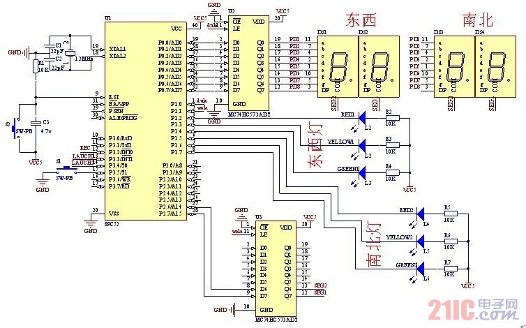
A steady, flexible, and convenient traffic light control system is essential for effective traffic management. In practice, many traffic lights operate on a time interval basis. This design allows for the adjustment of switching times for traffic lights during...
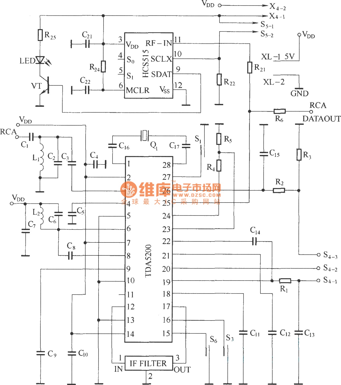
The TDA5200 is a low-power, single-chip ASK superheterodyne receiver circuit. It operates within two frequency blocks: 868 to 870 MHz and 433 to 435 MHz. This circuit is highly integrated, requiring minimal external components while offering excellent functionality. It...