
555 Variable Frequency Square Wave Generator

The 555 Variable Frequency Square Wave Generator is a versatile circuit that utilizes the 555 timer IC to generate square wave signals with adjustable frequency. The circuit typically consists of a few key components: a 555 timer, resistors, capacitors, and a power supply.
In its astable mode of operation, the 555 timer continuously switches between its high and low states, creating a square wave output. The frequency of the output signal can be modified by adjusting the values of the resistors and capacitors connected to the timer. Specifically, the frequency (f) can be calculated using the formula:
\[ f = \frac{1.44}{(R1 + 2R2) \cdot C} \]
where R1 and R2 are the resistances in ohms, and C is the capacitance in farads. By changing R1, R2, or C, the frequency of the output can be varied, allowing for a wide range of square wave frequencies to be generated.
The output signal can be utilized in various applications, including driving LEDs, generating audio tones, or providing clock pulses for digital circuits. The circuit can be powered using a DC source, typically ranging from 5V to 15V, making it suitable for a variety of projects.
For stability and performance, it is important to use high-quality components, particularly for the capacitors, as this can affect the accuracy of the frequency output. Additionally, proper layout practices should be followed to minimize noise and interference in the generated signal.
Overall, the 555 Variable Frequency Square Wave Generator is an effective and straightforward solution for generating adjustable square wave signals in electronic applications.555 Variable Frequency Square Wave Generator This simple 555 Variable Frequency Square Wave Generator produces a variable frequency output of.. 🔗 External reference
Related Circuits
Are you familiar with the basics and applications of the 555 timer IC? Are you looking for a book that provides all these basics? If so, CircuitsToday has started an online store where you can purchase books on the...
These are plans for an EMP generator. It utilizes flash circuits from disposable cameras to power the coil. An instructable will be created soon. The EMP generator design described involves utilizing the high-voltage flash circuits found in disposable cameras. These...
By utilizing a preamplifier with a short length of shielded cable and clip leads, signals that typically do not produce a readout can generate precise and stable readouts on the counter. A DPDT switch is incorporated to bypass the...
The circuit features a dual-core 556 timer IC and a light-emitting diode (LED) tube. The left half of the IC (556 1/2) comprises resistors R1, R2, capacitor C1, etc., generating a frequency of approximately 2 Hz in a multivibrator...
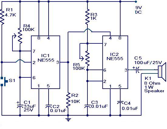
The primary component of this circuit is a doorbell utilizing two NE555 timer ICs. When the switch S1 is momentarily pressed, the speaker produces a bell sound, which is determined by the time period of the monostable multivibrator configured...
Stepper motors are a frequently discussed topic. This circuit converts a clock signal from a square wave generator into signals that have a 90-degree phase difference, which are necessary for driving the stepper motor windings. The trade-off for this...