
556 photoelectron pulse detectors omission

The photoelectron pulse missing detection circuit is engineered to reliably detect interruptions in light paths, making it suitable for applications where monitoring of light signals is critical. The H13B1 optoelectronic switch serves as a sensitive light sensor, responding to the presence or absence of light within its defined slot. The dual time base circuit, utilizing the 556 timer IC, is pivotal for timing and pulse generation, enabling precise control over the detection and response mechanisms.
The integration of RC components in the one-shot multivibrator configuration allows for flexible timing adjustments. By modifying the resistance values of R1 and R2 or changing the capacitance of C2, the user can calibrate the circuit to accommodate various environmental conditions or specific application requirements. The SCR (Silicon Controlled Rectifier) acts as a switch that can handle high power loads, ensuring that the output response is robust enough to activate alarms or control other devices in response to light interruptions.
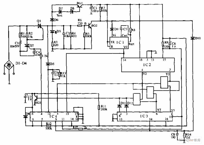
The design's high duty cycle of 99% ensures that the H13B1 luminous tube remains illuminated most of the time, providing a clear visual indication of the circuit's operational status. This feature is particularly useful in environments where immediate visibility of the circuit's performance is necessary. Overall, the circuit is a sophisticated solution for detecting light interruptions, offering adjustable timing capabilities and reliable output responses for a variety of applications. As shown in FIG photoelectron pulse missing detection circuit. The detector consists of optoelectronics slotted switch H13B1, dual time base circuit 556 with some RC components constituting the one-shot multivibrator and other components. It opened a few millimeters slots between the arc tube and the photosensitive optoelectronic switch H13B1 tube inside. When the external light blocking object into its slot, H13B1 internal photodiode beam path is cut off due to a high-impedance so IC1-2 (1/2 556) pulse signal detector due to lack of a reset signal and output high into the temporary steady state, transient stability corresponding time td 1.1RwlC2, and adjust W1 can be changed td.
If the signal interruption longer than the temporary stabilization time of magic, the IC1-2 reset, active low output enable pin BG1 end, SCR SCR conduction, so that the corresponding load RL is energized, or the power supply circuit is disconnected, or issue alarm signal. Multivibrator IC1-1 (1/2 556) and R1, R2, C1 and other components, the oscillation frequency of f 1.44/(R1 + 2R2) C1, the icon parameter corresponding oscillation signal frequency of approximately 2.5kHz 99% duty cycle, high duty cycle of the pulse signal driving the H13B1 luminous tube lighting.
Related Circuits

Powering up twin digital Sony DSC-V1 cameras simultaneously can achieve remarkable synchronization within milliseconds. This is accomplished through the use of dual Sony wired remotes that short the ACC port LANC signal conductor to the ACC port ground. Further...

A low power H-bridge may be necessary for driving a motor. The 555 integrated circuit (IC) can handle a load of up to 200 mA, either sourcing or sinking, making it a potential driver if the output can be...
The pulse telephone 160 168 controller circuit is depicted above. This controller can be installed either on the telephone or on the switchboard of the trunk line. It effectively prevents unauthorized dialing of numbers 160 and 168. Diodes D1...

This circuit is quite effective for testing or operating counters and stepping relays, as it eliminates the need for manually setting a switch for the desired number of pulses. By pressing the appropriate switches S1 to S9, one can...
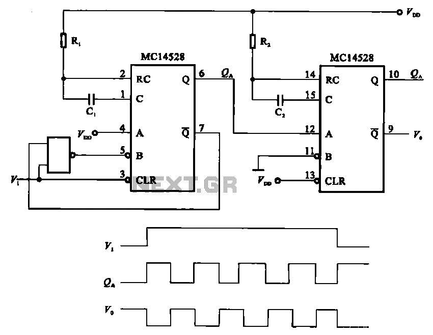
The pulse generating circuit monitors signals using monostable flip-flops. It generates a single-shot output signal based on the input pulse signal. A key signal from the monostable flip-flops is represented in a formula, with the input (V1) and output...
Utilizing technology developed by Dr. Royal Rife, Gary Wade has created an ultrasound scanning device that effectively eliminates harmful microbes and pathogens through the application of multiple frequencies. Numerous articles on this site provide detailed information on this topic. The...