
5V FET Voltage Regulator

The voltage regulator circuit utilizes a linear voltage regulator, such as the LM7805, which is designed to maintain a constant output voltage despite fluctuations in the input voltage or load conditions. The circuit typically includes input and output capacitors to enhance stability and transient response.
The input capacitor, often a 0.33 μF ceramic capacitor, is connected between the input pin of the regulator and ground. This capacitor helps to filter out high-frequency noise from the power supply and provides a stable input voltage to the regulator. The output capacitor, usually a 0.1 μF ceramic capacitor, is connected from the output pin to ground, which aids in improving transient response and stability of the output voltage.
To set up the circuit, the unregulated input voltage (greater than 5V) is connected to the input pin of the regulator. The output pin is connected to the load that requires a stable 5V supply. The ground pin of the regulator must be connected to the common ground of the circuit to ensure proper operation.
In addition to these components, it is advisable to include a heat sink on the regulator, especially if there is a significant voltage drop from the input to the output, which can generate heat. The performance of the circuit can be further enhanced by ensuring that the regulator operates within its specified input voltage range and load current limits to avoid thermal shutdown or damage.
Overall, this voltage regulator circuit is suitable for various applications requiring a stable 5V power supply, such as powering microcontrollers, sensors, and other electronic devices.This voltage regulator circuit gives a stable 5V output from unregulated inputs (more than 5V). The stability of the output voltage is good enough, only change. 🔗 External reference
Related Circuits
This circuit is a conventional Pierce type oscillator that utilizes a JFET. It employs fundamental mode crystals and demonstrates decent performance and reliability. The Pierce oscillator is a popular configuration for generating stable oscillations, particularly in applications requiring a stable...
The FM302E-I-type FM transmitter exciter is utilized in Japan's NEC HPB a 1210 motherboard. It features direct carrier frequency modulation, phase-locked frequency stabilization, and frequency synthesis. The preamplifier (BLF-177 FET) is directly driven by an actuator, achieving a maximum...
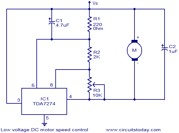
The circuit diagram illustrates a low voltage/low power DC motor speed controller utilizing the TDA 7274 integrated circuit from ST Microelectronics. The TDA 7274 is designed for low voltage and low power applications, featuring an internal voltage reference, a...

This design circuit is a tachometer circuit based on the LM2907 integrated circuit, which can provide zero-crossing data to a digital system. At each zero crossing of the input signal, the charge pump alters the state of capacitor C1...
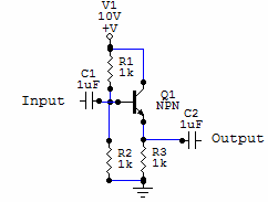
Two examples of the most common types of Voltage followers (buffers). You can find some theory behind them in our amplifier gain and buffer amplifier pages. This first circuit is a very simple one transistor voltage follower. Consists of...
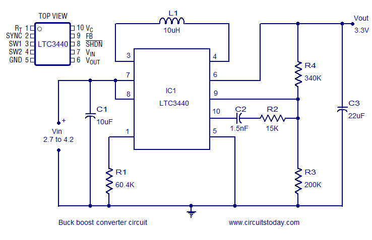
A simple and highly efficient buck-boost converter is implemented using the LTC3440 integrated circuit. The output voltage is set at 3.3V, while the input voltage range can vary from 2.7V to 4.2V. The LTC3440 is a synchronous buck-boost converter designed...