
Pierce XTAL Oscillator Using JFET
The Pierce oscillator is a popular configuration for generating stable oscillations, particularly in applications requiring a stable frequency reference. In this design, the JFET (Junction Field Effect Transistor) serves as the active device, providing high input impedance and low noise characteristics, which are essential for effective oscillation.
The circuit typically consists of a crystal resonator, which determines the oscillation frequency by its physical properties. The fundamental mode crystals used in this configuration ensure that the oscillator operates at the desired frequency with minimal harmonic distortion. The JFET is configured in a feedback loop that allows a portion of the output signal to be fed back to the input, sustaining oscillations.
Key components of the circuit include the JFET, the crystal, and passive elements such as resistors and capacitors that set the gain and phase shift necessary for oscillation. The resistors help in biasing the JFET, while capacitors are used for coupling and filtering purposes.
To enhance performance, proper selection of component values is crucial. The values of the resistors and capacitors are determined based on the characteristics of the JFET and the crystal used, ensuring that the circuit operates within the desired frequency range with adequate amplitude and stability.
Overall, the Pierce type oscillator circuit is valued for its simplicity, effectiveness, and reliability, making it suitable for various applications, including clock generation, frequency synthesis, and signal modulation.This circuit is conventional Pierce type oscillator that uses a JFET. The circuit uses fundamental mode crystals. It has decent performance and reliability if. 🔗 External reference
Related Circuits
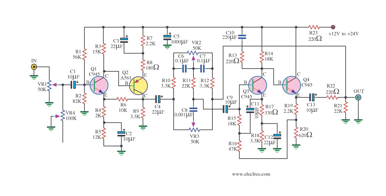
If you have old electronic equipment that has been around for many years, it is beneficial to build a good electronic project. Guidance is requested regarding a pre-tone control circuit for this purpose. A pre-tone control circuit is an essential...
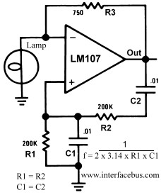
This circuit generates a 10Hz sine wave using a minimal number of components, based on the specified component values. The active components are generic and can be substituted as needed. The passive component values determine the frequency and should...
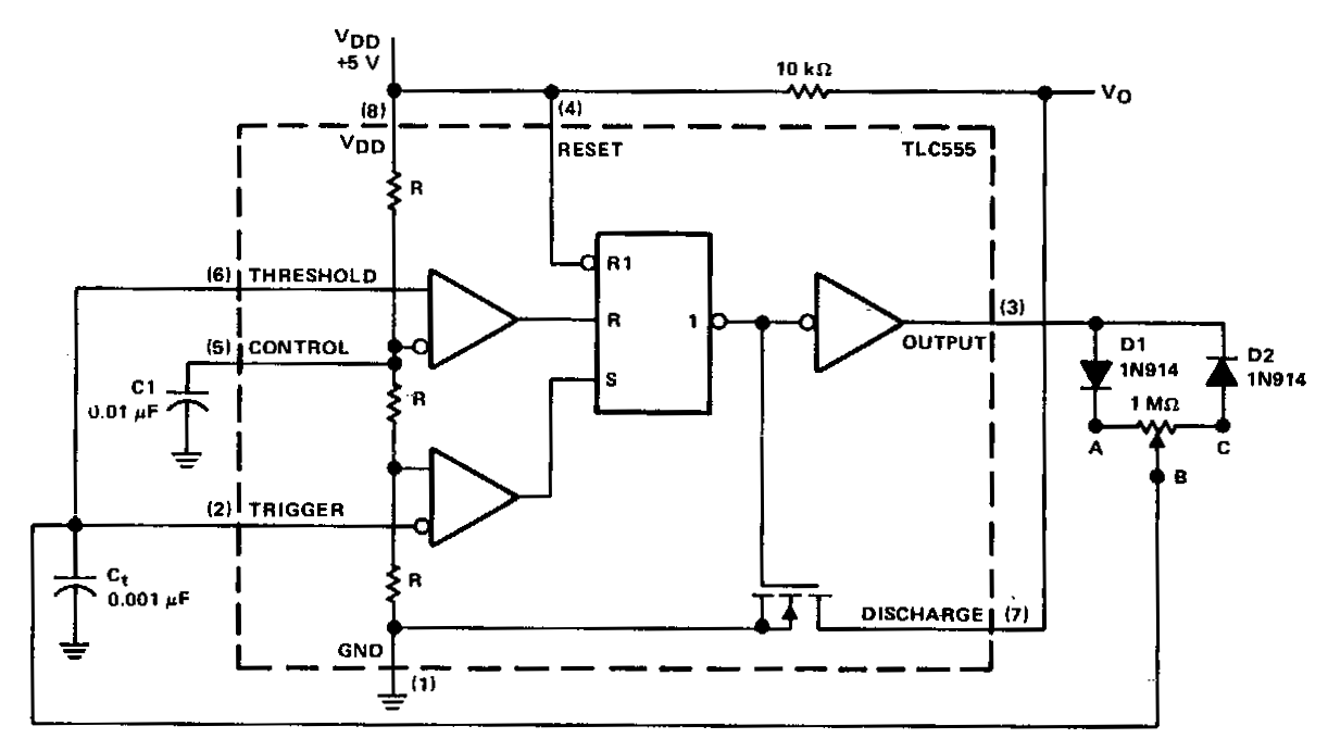
In a basic astable timer, the timing periods 11 and 12 are not independently controlled. This lack of control complicates the maintenance of a constant period, T, if either 11 or 12 is varied. In this circuit, the charge...
This is a dry cell battery charger circuit designed to charge batteries over a period of approximately 12 hours. When powered by a 9-volt supply, the circuit is configured to accommodate AA-sized batteries. If C or D-sized batteries are...

A simple linear voltage-controlled amplifier can be constructed with one operational amplifier (op amp) and two junction field-effect transistors (JFETs). This amplifier can achieve an 80-dB dynamic control range with less than ±0.2% linearity error for 0 V. The described...
The circuit consists of a lag comparator with amplifier A1 and an inverting integrator A2. The charging and discharging time constant is determined by the integral resistors (R1 + RP1) and the capacitor C1. Diodes VD1 to VD5 form...