
5V Regulated Power Supply

The 5V regulated power supply circuit is designed to provide a stable output voltage of 5 volts, which is essential for powering various electronic devices and circuits. This type of power supply typically utilizes a transformer, a rectifier, and a voltage regulator to ensure that the output voltage remains constant, even when the input voltage or load conditions change.
The circuit begins with an AC power source, which is connected to a step-down transformer. The transformer reduces the high AC voltage to a lower AC voltage suitable for the application. The output of the transformer is then fed into a rectifier, which can be a full-wave or half-wave rectifier, depending on design requirements. The rectifier converts the AC voltage into pulsating DC voltage.
Following the rectification process, the pulsating DC voltage is smoothed using a filter capacitor. This capacitor charges during the peaks of the rectified voltage and discharges during the troughs, effectively reducing the ripple voltage and providing a more stable DC output.
To achieve the desired output voltage of 5V, a linear voltage regulator, such as the 7805, is employed. The 7805 regulator takes the smoothed DC voltage and outputs a regulated 5V, ensuring that fluctuations in the input voltage or load do not affect the output voltage. Additional capacitors may be placed at the input and output of the regulator to improve transient response and stability.
This power supply circuit is widely used in various applications, including microcontroller circuits, sensor systems, and communication devices, where a reliable 5V supply is crucial for proper operation. Proper heat dissipation measures should also be considered, as linear regulators can generate heat when there is a significant voltage drop across them, especially under higher load conditions.5v regulated power supply circuit, 5v power supply circuit, regulated power supply circuit diagram.. 🔗 External reference
Related Circuits
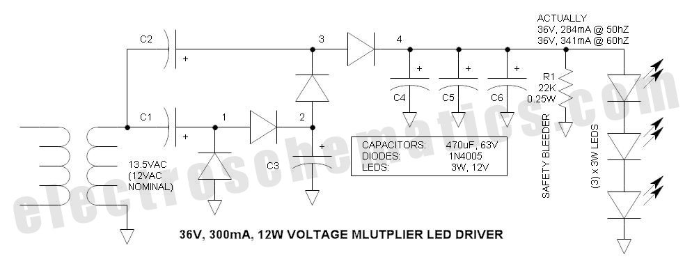
This power supply circuit is designed around a standard 12VAC landscape lighting transformer. The availability and selection of transformers have long posed challenges for experimenters, often leading them to use potentially hazardous off-line capacitor-limited power supplies. However, the widely...
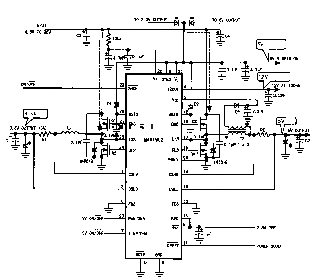
Multi-output power supply circuit (MAX1902). This circuit illustrates the power supply configuration for a notebook computer motherboard, utilizing the MAX1902 chip for power control. It is designed to convert the battery's DC voltage into multiple DC voltage outputs. The multi-output...
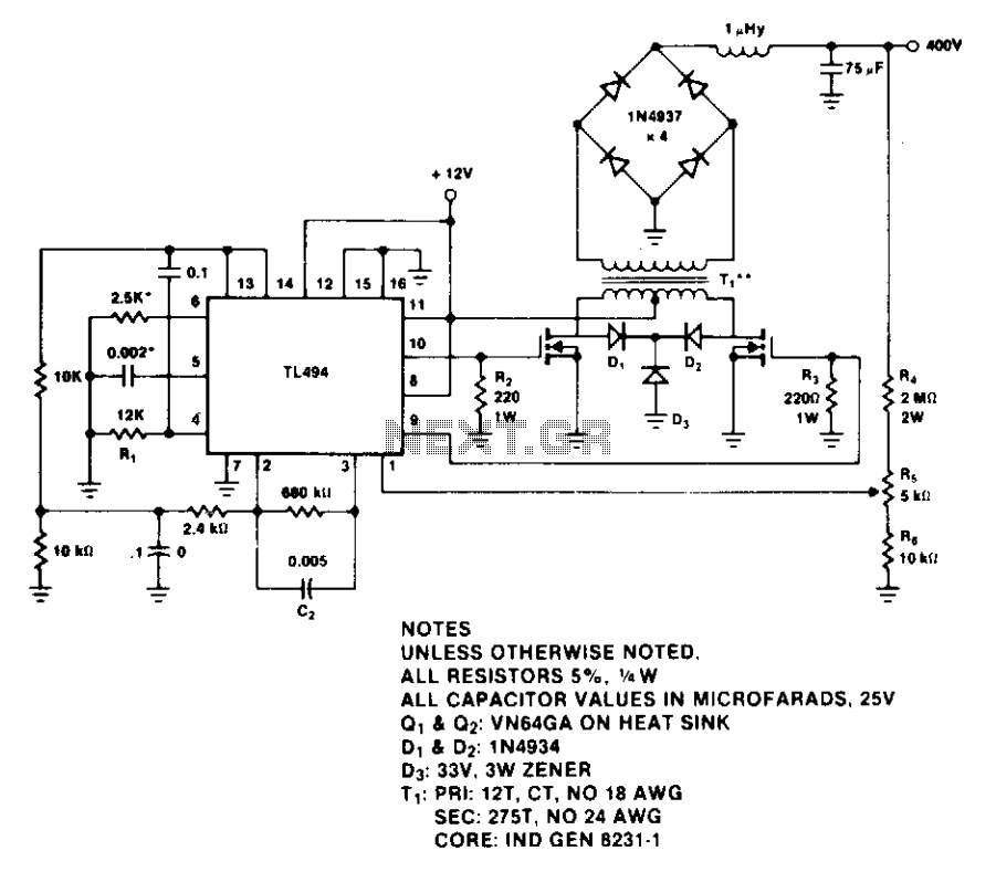
The design provides a regulated output of 400 V and 60 W. The TL494 switching regulator controls the operating frequency and output voltage regulation. Resistor R1 and capacitor C1 set the switching frequency, which is approximately 0.5 to 100...
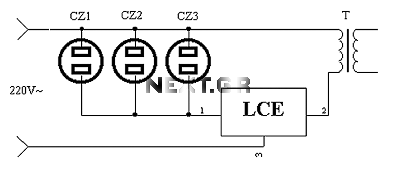
The application circuit operates as depicted below. It typically utilizes a shared TV antenna amplifier and an isolated power switch for the user. There are instances when the TV may not function, yet the antenna amplifier remains powered, leading...
This circuit is essentially a crystal radio equipped with an audio amplifier that demonstrates considerable sensitivity, successfully receiving multiple strong stations in the Los Angeles area using a minimal 15-foot antenna. Employing a longer antenna can enhance signal strength;...
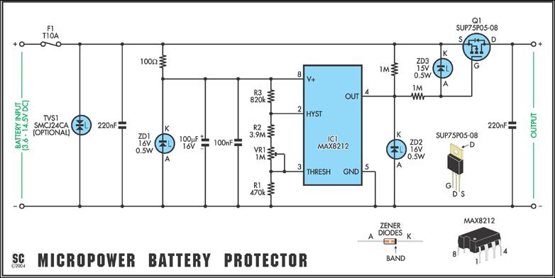
Protect expensive batteries from discharge damage with this mini-sized electronic cutout switch. It consumes minimal power and can be adapted to accommodate a wide range of battery voltages. In May 2002, Silicon Chip introduced the "Battery Guardian," a project...