
Shared antenna amplifier power since the controller circuit diagram

The circuit design incorporates a shared TV antenna amplifier that enhances signal reception for multiple televisions. The amplifier is powered through a user-isolated switch, which prevents it from drawing power unnecessarily when not in use. The LCE module serves as an intelligent control mechanism that monitors the power status of the connected televisions.
When a television is connected to one of the designated sockets (CZ1, CZ2, CZ3, etc.), the LCE module detects the load and automatically closes the power switch for the shared antenna amplifier. This action ensures that the amplifier is only powered when at least one television is in operation, thereby reducing energy wastage.
The LCE module can be designed to accommodate additional sockets, allowing for flexibility in installation while remaining within the power limits of the LCE unit. This arrangement not only optimizes energy consumption but also simplifies user experience by eliminating the need for manual switching. The overall circuit provides an efficient solution for households with multiple televisions, enhancing both convenience and energy efficiency.Application circuit works the device as shown below. Generally shared TV antenna amplifier and power switch user is isolated. Sometimes no one can work the TV, the antenna ampl ifier is still powered on, the power consumed in vain. Other times, it may have more than one television program is being received, and shared antenna amplifier power switch is not closed, of course, not so good reception. Using LCE module can be easily controlled automatically. When the socket CZ1 TV used, CZ2, CZ3 (of course, can also be designed to install more electrical outlets, so long as the LCE power allow) any one inserted TV power switch is closed, the shared antenna amplifier the power supply automatically.
Then they will not waste energy, without affecting the TV user, and does not require special management.
Related Circuits
Power supplies designed for use with TTL logic circuitry must protect against over-voltage, which can rapidly damage TTL chips. The duration of over-voltage that can harm TTL chips is too short to activate any conventional fuse, necessitating the use...
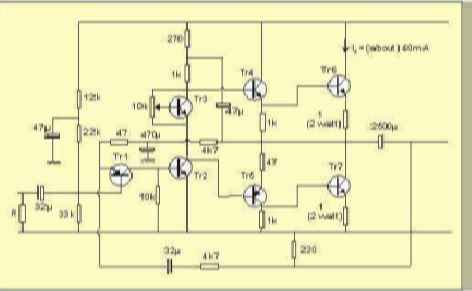
The table below illustrates the expected voltages when utilizing a 24V supply, with the variable resistor adjusted to provide an output current of approximately 40mA. The circuit operates with a 24V DC power supply, where a variable resistor (also known...
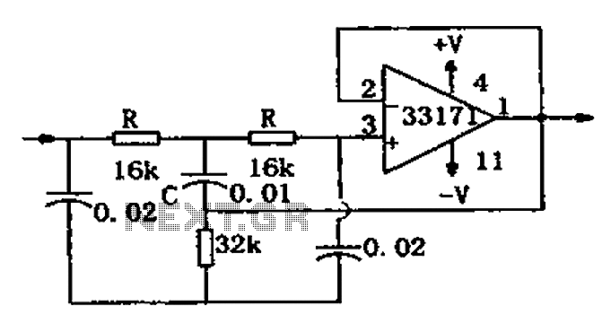
The trap circuit utilizes a high-performance operational amplifier, MC33171, to create the trap. This device features a wide bandwidth and high conversion rate. The component values can be modified by adjusting the capacitance of capacitor C and the resistance...
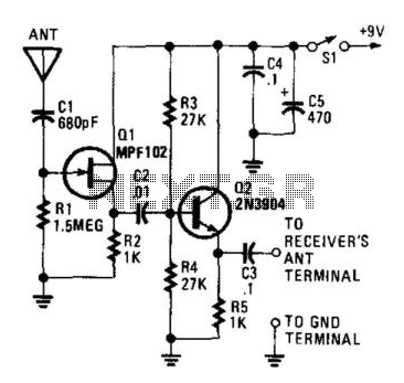
This circuit is designed to enable a short pull-up antenna to function similarly to a long wire antenna, without providing any voltage gain. The circuit enhances the receiver's performance only if the signal at the antenna is sufficiently strong...
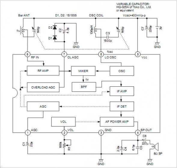
The CXA1619BM and CXA1619BS are one-chip FM/AM radio integrated circuits developed by Sony Corporation. These ICs are intended for use in radio-cassette tape recorders and headphone tape recorders, offering a variety of functions. The CXA1619BM and CXA1619BS are designed to...
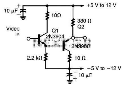
This circuit has demonstrated effectiveness as a video buffer and can easily drive a 75-ohm load to a 1.5-V peak-to-peak output. The bandwidth exceeds 20 MHz, and the DC offset is less than 0.05 V, attributed to the difference...