
5v regulated solar cell power supply circuit diagram

Component Parts List:
- R1 = 22 ohm, 1W
- R2 = 270 ohm
- R3 = 220 ohm
- R4 = 715 ohm, 1%
- R5 = 3.57K, 1%
- R6 = 1.40K, 1%
- R7 = 1.47K, 1%
- C1 = 0.1 F, ceramic
- C2 = 0.1 F, ceramic
This battery charger circuit is regulated and adjustable, making it suitable for charging most NiCAD batteries. It can accommodate single or multiple battery cells connected in series or parallel, with a maximum battery voltage of 18V. Power transistors Q1 and Q2 are configured as series regulators.
A load cell amplifier can be constructed to reduce costs, as commercial options are often priced between $100 and $300. The proposed load cell amplifier utilizes the AMP04 or INA125 components.
The solar-powered battery charging circuit operates efficiently in bright sunlight, providing a reliable power source for charging batteries. The use of diodes ensures that the current flows in the correct direction, preventing backflow that could damage the solar panel or the batteries. The inclusion of capacitors helps smooth out the rectified voltage, providing stable output levels.
The circuit's design allows for easy adjustment and regulation, making it versatile for different applications, particularly for charging various battery types. The specified resistors and capacitors are selected to optimize performance while maintaining cost-effectiveness.
Overall, this schematic presents a practical solution for harnessing solar energy to charge batteries, demonstrating the integration of renewable energy sources in electronic applications.Powered with solar panel, the circuit will give you 5V pure regulated DC voltage. The circuit is made up of an oscillator transistor as well as a regulator transistor. The solar panel charges the battery when sunlight is bright enough to generate a voltage above 1. 9v. A diode is necessary between the panel and also. This is the schematic diagram of solar powered mobile phone battery charger. The circuit is designed to charge the battery from a source with a lower voltage. Do not use it to charge the battery with the same or lower voltage than the voltage which is generated by the solar panel. For proper operation of. This circuit generates 3 source regulated voltages applying a minimum of electronic parts. The output DC voltage are +12V ; +5V and -5V. Diodes D2 and D3 conduct full-wave rectification, at the same time charging capacitor C2 on each halves of the alternating current cycle.
At the same time, diode D1 with capacitor C1, and. The following diagram is the battery charger schematic for 6V Gel Cell battery type. Component Parts List: R1 = 22 ohm, 1W R2 = 270 ohm R3 = 220 ohm *R4 = 715 ohm, 1% *R5 = 3. 57K, 1% *R6 = 1. 40K, 1% *R7 = 1. 47K, 1% C1 = 0. 1 F, ceramic C2 = 0. 1 F, ceramic. This battery charger circuit is regulated and adjustable to make this circuit able to charge the mosto NiCAD battery. This circuit will work for single cell or multi battery cell which connected with series/parallel connection.
The maximum voltage of the batteries should be 18V maximum. Power transistors Q1 and Q2 are connected as series regulators. I`ve found some interesting schematic of Load Cell amplifier. As we know, load cell amplifier is pretty expensive with fair price range of 100-300 USD. You may built your own load cell amplifier to get the lower cost. Load Cell Amplifier using AMP04: source: Load Cell Amplifier using INA125: source: source: 🔗 External reference
Related Circuits
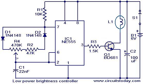
The circuit presented here is designed to control the brightness of low-power incandescent lamps. It utilizes the NE555 integrated circuit, configured as an astable multivibrator with a variable duty cycle. The output from the IC is connected to the...
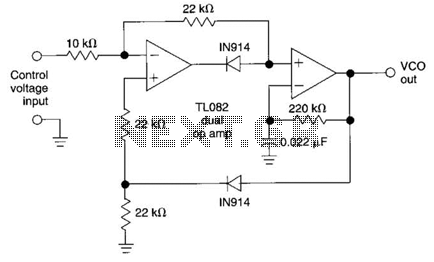
This circuit utilizes the AD639 universal trigonometric function generator from Analog Devices to transform a triangle waveform, which serves as the fundamental waveform of the VCO, into a low-distortion sine wave. By operating the AD639 in its frequency tripler...
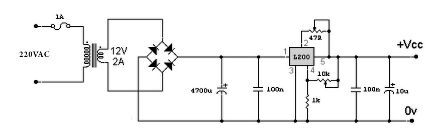
A variable power supply based on the L200 IC, where the output voltage is controlled by a 10K variable resistor. The output voltage ranges from approximately 3 to 15 volts, with a current output ranging from a minimum of...
Four simple 12V power supply circuits are designed to provide output voltages close to 12V. The first power supply circuit utilizes a BD139 transistor, a zener diode, and several passive components. Each schematic is straightforward to assemble and will...
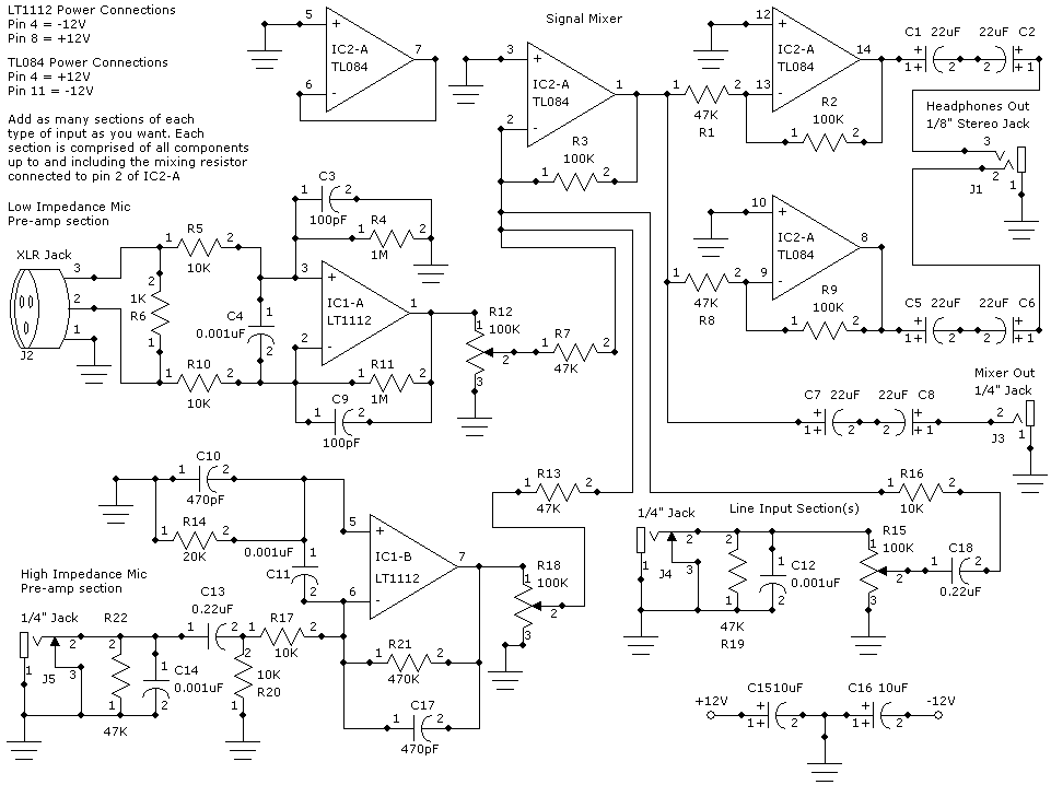
This weblog focuses on electronic circuit schematics, PCB design, DIY kits, and diagrams for various electronic projects. It features a mixer that demonstrates how to create microphone pre-amplifiers suitable for both low and high impedance microphones. The design utilizes...
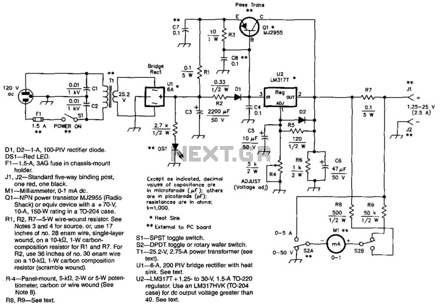
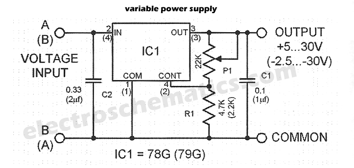
This power supply utilizes an LM317J adjustable regulator along with an MJ2955 pass transistor. Q1 and U2, as well as U1, should be equipped with heatsinks. A suitable heatsink would typically measure 4" x 4" x 1" with fins,...