
+5V Supply Circuit

The power supply circuit is designed to convert the AC voltage from a standard wall transformer into a usable DC voltage suitable for various electronic applications. The wall transformer (T2) steps down the mains voltage to 12 volts AC, which is then rectified and filtered to produce a stable DC output.
The circuit typically includes a rectifier, often a bridge rectifier configuration, which consists of four diodes arranged in a bridge format to efficiently convert the AC voltage to pulsating DC. Following the rectifier, a smoothing capacitor is employed to filter out the ripples in the output voltage, providing a more stable DC level. The value of this capacitor is chosen based on the load current and the acceptable ripple voltage.
In addition to the basic components, a voltage regulator may be included to ensure that the output voltage remains constant despite variations in load current. This feature is particularly important in laboratory settings where precise voltage levels are required for testing purposes.
Moreover, the circuit may incorporate additional features such as fuses for overcurrent protection, indicator LEDs for power status, and adjustable resistors or potentiometers to allow for fine-tuning of the output voltage.
Overall, this power supply circuit is a fundamental component in electronic laboratories, providing a reliable source of power for testing and development of various electronic circuits. The power supply shown is designed to operate from a wall transformer. This circuit can be used in conjunction with a variable supply to test circuits in the lab, etc. T2 is a 12-V wall transformer.
Related Circuits
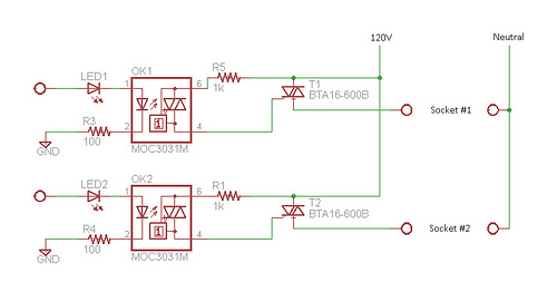
Many projects involve 120VAC and require relatively slow switching. While mechanical relays are commonly used in such situations, they are often avoided due to the presence of moving parts. Solid-state relays (SSRs) have been utilized previously, but their high...
This chapter contains circuit diagrams for various power supplies designed for pulsed solid-state lasers. These include units suitable for driving the widely used Hughes ruby and YAG rangefinder laser assemblies, one utilizing the flash from a disposable pocket camera,...
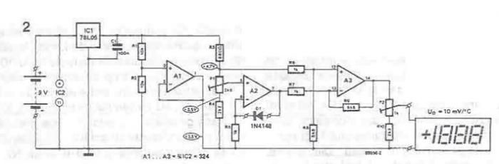
A simple thermometer can be constructed using operational amplifiers and a standard or protective diode, such as the 1N4148, as depicted in the electronic diagram below. A constant reference voltage is supplied to the non-inverting input of the operational...
I use the lm10 IC because it has a reference voltage and that’s useful for dc power supply. With two ICs can take different output voltage and amperage. This circuit is protected from short circuit. P2 is for controlling...
This is a low-cost 150-watt amplifier circuit with a diagram and schematic design utilizing two Darlington power transistors, TIP142 and TIP147. The 150-watt amplifier circuit is designed to provide high power output while maintaining cost efficiency, making it suitable for...
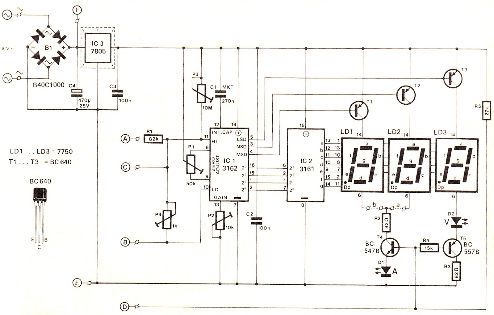
This voltage/current (V/I) display module is well-suited for integration into an existing DC power supply, providing precise readings of the set voltage or the current consumption of the load. The voltage measurement range features a decimal point indicator (LD3),...