
5V transformer less power supply

This transformerless power supply circuit is designed for low-power applications where isolation from the mains voltage is not a primary concern. The key components include a resistor (R1), a bridge rectifier (D1), a Zener diode, and a filter capacitor (C2).
Resistor R1 limits the current flowing through the circuit, ensuring that the downstream components are not subjected to excessive current levels. The choice of resistance value is critical, as it must be calculated based on the expected load current and the input voltage to maintain safe operating conditions.
The bridge rectifier (D1) consists of four diodes arranged in a configuration that allows AC mains voltage to be converted into pulsating DC voltage. This rectification process is essential for powering DC loads. The output of the rectifier is characterized by a ripple voltage, which can be smoothed out by the filter capacitor (C2).
The Zener diode is employed to regulate the output voltage to a precise 5V DC. It operates in reverse breakdown mode, maintaining a constant voltage across its terminals as long as the current remains within specified limits. This regulation is crucial for applications requiring stable voltage levels.
Capacitor C2 plays a vital role in filtering the rectified output. It charges during the peak voltage periods and discharges during the lower voltage intervals, thus reducing the ripple voltage and providing a more stable DC output. The capacitance value must be selected based on the load requirements and the level of acceptable ripple.
Overall, this circuit provides a compact and efficient solution for converting AC mains voltage to a low-voltage DC supply, suitable for powering small electronic devices. However, it is essential to consider safety and compliance with electrical standards, particularly when working with mains voltage.Here is the circuit diagram of a 5V transformer less power supply using minimum components. The working of this circuit is quite simple. Resistor R1 does the job of current limiting and bridge D1 rectifies the mains voltage. The Zener diode regulates the rectifier output to obtain a steady 5V DC and capacitor C2 acts as a filter. 🔗 External reference
Related Circuits
High Current Variable Power Supply Circuit Diagram. The widely used variable voltage regulator IC LM317 can handle a maximum current of only 1 ampere, making it unsuitable for applications requiring a high current variable power supply. The design of a...
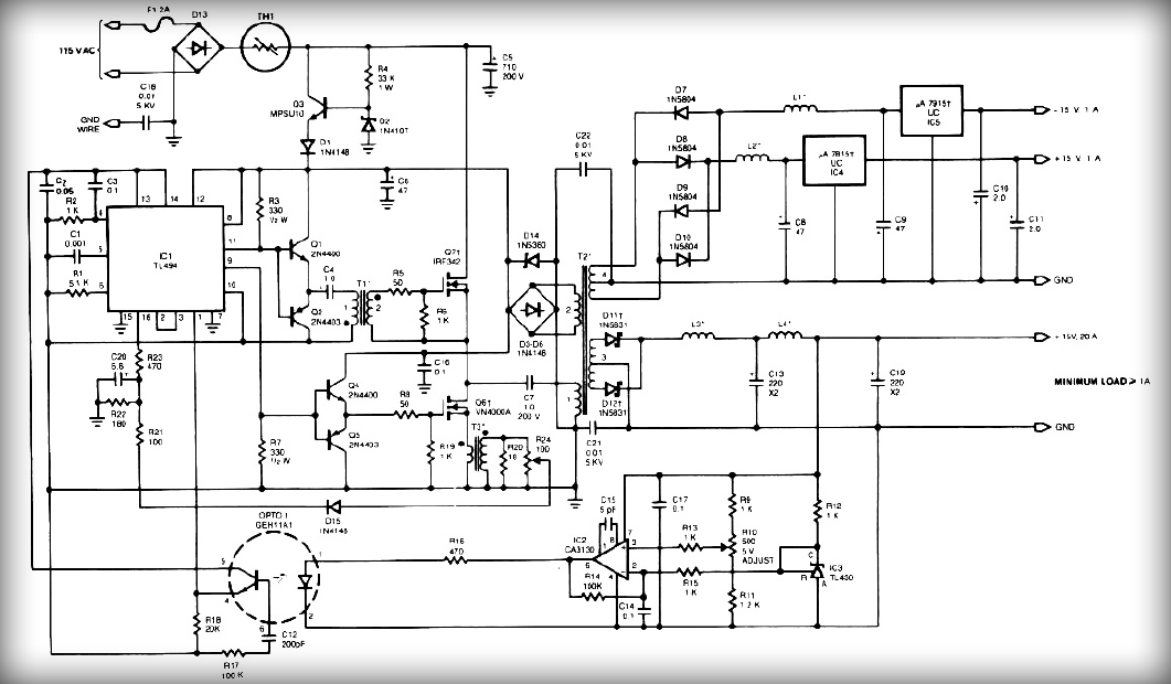
This power supply employs two VN400A 400-Volt MOSFETs arranged in a half-bridge configuration. The outputs provide +5V at 20A and +15V at 1A. Low-current outputs utilize three-terminal regulators, allowing for either 12 Volts or 15 Volts to be achieved...
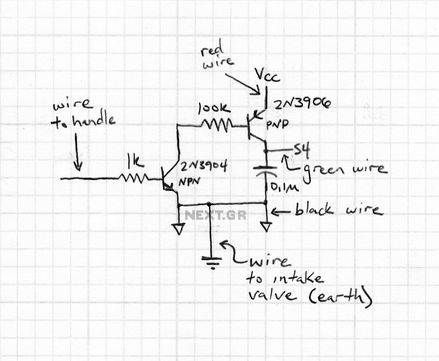
The circuit provides Automatic Level Control (ALC) feedback to a driver or utilizes signals from a directional coupler to drive power monitors or Standing Wave Ratio (SWR) lockout circuits. The design employs a pair of microwave diodes functioning as...
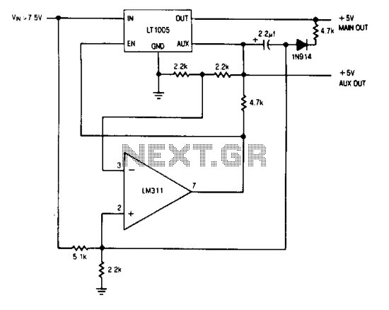
The auxiliary output powers the memory, while the main output powers the system and is connected to the memory store pin. When power goes down, the main output goes low, commanding the memory to store. The auxiliary output then...
Many circuits can be powered directly from the mains with the aid of a series capacitor (C1). The disadvantage of this approach is that usually only one half cycle of the mains waveform can be used to produce a...
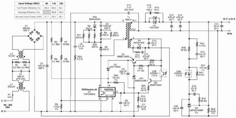
The TOP269EG off-line switcher integrated circuit (IC), designated as U1, can be utilized in a flyback configuration to create a simple and highly efficient power adapter for notebook laptops. The TOP269EG features an integrated 725 V MOSFET and a...