
Bridge circuit

The described circuit is designed to measure low resistances with high precision, specifically in the range from 5 ohms down to 0.1 ohm. Such measurements are crucial in various applications, including material testing, component characterization, and quality control in manufacturing processes.
The circuit typically employs a four-wire (Kelvin) measurement technique to eliminate the effects of lead and contact resistances, which can significantly influence the accuracy of low-resistance measurements. The configuration consists of two pairs of wires: one pair carries the current through the resistor under test, while the other pair measures the voltage across the resistor. This method ensures that the voltage measurement is taken directly across the resistor, thereby providing an accurate reading of its resistance.
Key components of the circuit may include a precision current source, a high-resolution voltmeter or an analog-to-digital converter (ADC) for digital readings, and a microcontroller for processing the measurements and displaying results. The current source is often adjustable to allow for different measurement ranges and to ensure that the current level does not exceed the power rating of the resistor being tested.
In addition, the circuit can incorporate filtering and amplification stages to enhance measurement stability and reduce noise, which is particularly important when dealing with very low resistance values. The output can be presented in various formats, such as a digital display or transmitted to a computer for further analysis.
Overall, the design of this low-resistance measurement circuit emphasizes accuracy, stability, and ease of use, making it a valuable tool in both laboratory and industrial environments.For measurement of resistances from about 5 ohms down to about 1/10 ohm A very practical circuit.
Related Circuits
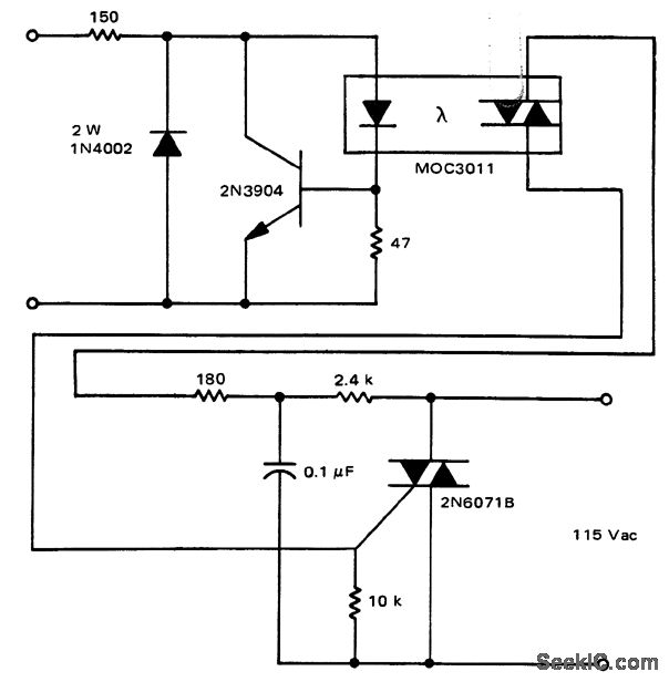
A solid-state relay circuit features an input protection mechanism utilizing the MOC3011 triac driver. The input voltage for the protection circuit can range from 3 to 30 volts DC, as noted by Motorola Semiconductor Products Inc. The solid-state relay (SSR)...
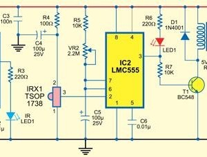
This type of infrared proximity circuit is commonly utilized as an electric switch where physical contact is undesirable for hygiene reasons. For instance, infrared proximity sensors are frequently found in public drinking fountains and washrooms. The straightforward circuit described...
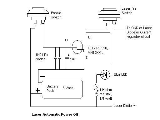
Here is the automatic laser power-off circuit schematic. This circuit features a visible power indication. In this case, the ground is connected on one side. The automatic laser power-off circuit is designed to enhance safety and efficiency in laser applications...

Achieving optimal performance from circuits used in third- and fourth-generation wireless systems necessitates tighter integration of previously separate tools. A degree of software synergy is crucial when designing circuits for modern wireless systems that utilize advanced modulation techniques alongside...

The FIG load test is a control circuit designed for external loads up to 10A, commonly utilized in drive test power applications, power amplifiers, LED solenoids, and relays. It is capable of handling various resistive loads and features a...
The decision to use electric power was made due to its quieter operation, lack of odor, and ease of carrying the bike up a flight of stairs. The selected conversion kit is manufactured by Currie. Although factory service is...