
6-Band Graphic Equalizer circuit

The EQ-2 circuit functions by dividing the audio frequency spectrum into six distinct bands, allowing for precise control over the tonal quality of the audio signal. Each band features a dedicated fader, which enables the user to adjust the gain for that particular frequency range. The faders provide a visual representation of the adjustments made, facilitating easier manipulation during audio mixing or sound reinforcement.
The circuit typically employs operational amplifiers (op-amps) in a band-pass filter configuration for each frequency band. The design ensures that only the desired frequency range is affected by the adjustment of the corresponding fader. The flat gain position at the center of the fader ensures that the audio signal remains unaltered when no adjustments are made.
For the implementation of stereo operation, two identical EQ-2 circuits are used, one for the left audio channel and one for the right. This configuration maintains the stereo image and ensures that both channels can be equally adjusted to achieve a balanced sound output.
The EQ-2 circuit is suitable for various applications, including home audio systems, professional sound reinforcement, and recording studios. Its flexibility and user-friendly interface make it a valuable tool for audio engineers and enthusiasts seeking to enhance their sound mixing capabilities.The EQ-2 it is a circuit of graphic equalizer 6 band of regulation. Each band is regulated from the potesometers RV1-6, that are, for better optical indicate of regulations, Fader. This does not mean that we cannot him replace with simply potesometer. In the center of regulation potesometer, the gain is null (flat), but in terminal has +/- 15 db, boost or cutting off, respectively.
For stereo operation, it will be supposed two times.. 🔗 External reference
Related Circuits
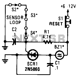
A string of three series-connected, normally closed switches is connected across the gate of a silicon-controlled rectifier (SCR). When one switch opens, the SCR is triggered through resistor R1, activating an alarm. The alarm is designed to be of...
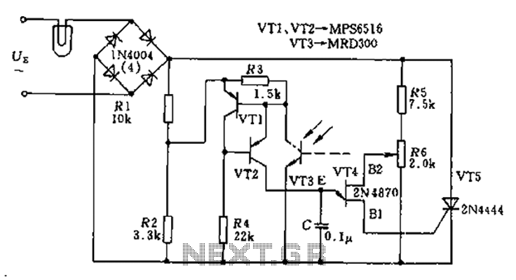
The circuit utilizes a thyristor-based AC automatic voltage regulator to stabilize the brightness of lamp L. A diagonal line connects the thyristor to the T5 bridge. The trigger pulse for the thyristor is generated by a single-junction transistor, VT4....
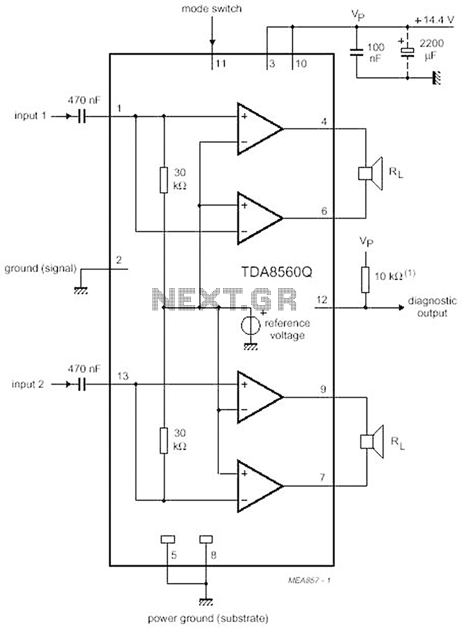
The proposed scheme is straightforward, requiring only a few external electronic components, making it suitable for car audio construction. The output power ranges from 2 to 4 Ohms, providing 2 x 30 W (with a maximum of 2 x...
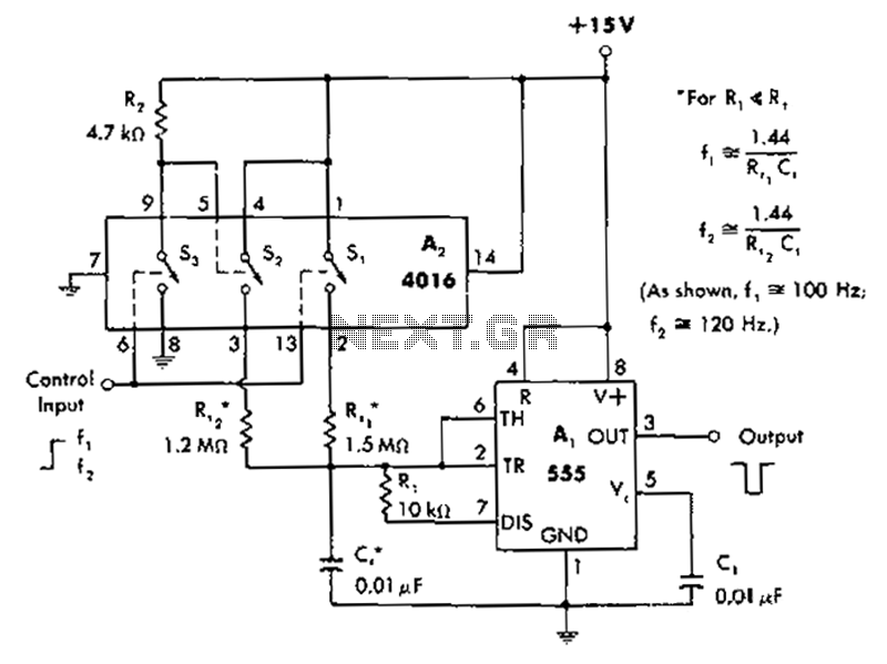
A circuit diagram controls the timing based on the input line state. When the input line is high, the 4016 CMOS analog switches select the timing of a 1.5 megohm resistor (Rt1) to produce negative output pulses at a...
This is a small circuit designed as an insect repellent, targeting mosquitoes and birds by producing high-frequency audio signals. These signals interfere with the hearing of insects, making it unbearable for them, causing them to flee. The operation of...
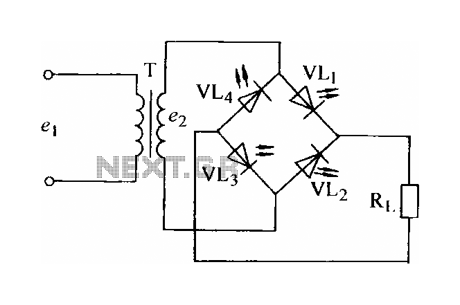
In certain applications, the current from a non-rectified voltage power supply circuit is insufficient. A light-emitting diode (LED) rectifier circuit can be employed to address this issue, serving as a power indicator. It is important to ensure that the...