
6-Channel Running Light

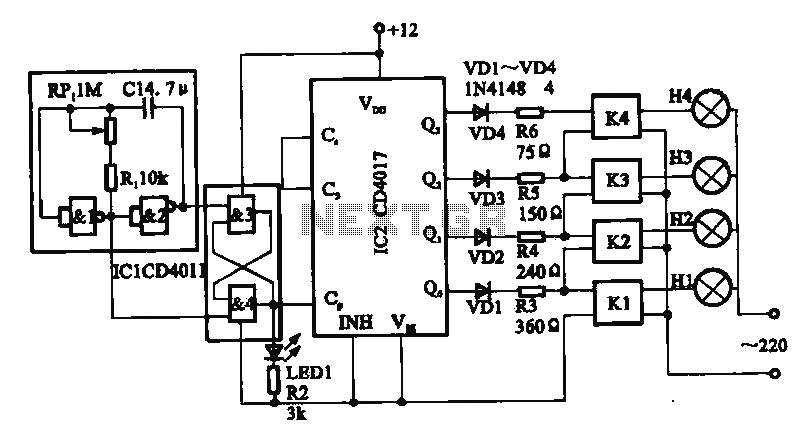
The running light circuit is designed to create a sequential lighting effect using seven LEDs. The primary components include two integrated circuits which serve different functions: one IC acts as a timer while the other operates as a decade scaler. The timer IC is responsible for generating timing pulses that control the sequence of the LEDs, ensuring that they light up in a specific order.
A resistor is included in the circuit to limit the current flowing through the LEDs, preventing them from drawing excessive current that could lead to damage. The value of this resistor is selected based on the forward voltage and current specifications of the LEDs used.
The capacitor in the circuit works in conjunction with the timer IC to establish the timing intervals between the LED activations. By charging and discharging, the capacitor helps to determine how long each LED remains illuminated before the next one in the sequence turns on.
The decade scaler IC is crucial in this circuit as it divides the input frequency from the timer IC by ten, allowing for a controlled and manageable sequence of LED activations. This IC ensures that the LEDs light up in a staggered manner, creating a visually appealing running light effect.
Overall, this running light circuit is an effective demonstration of basic electronic principles, integrating timing, current control, and sequential logic to achieve a dynamic lighting display.The circuit of the running light comprises two integrated circuits (ICs), a resistor, a capacitor and seven light-emitting diodes (LEDs), Decade scaler IC.. 🔗 External reference
Related Circuits
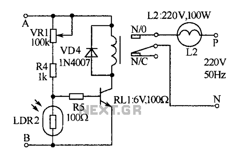
Light Switch. This is a light switch or light-activated relay circuit. The relay activates when the light-dependent resistor (LDR) is uncovered and deactivates when the LDR is covered. It is adjustable for sensitivity and includes an LED indicator. This light-activated...
The receiver, as depicted in the figure, assists patients in avoiding missed audio signals during the daytime. The receiver operates independently, and the lighting will automatically turn off. At night, the lighting signal receiver activates simultaneously with the patient's...

The complete hardware schematic of the Night Light Saver V6.0 includes an AC line protected by a 1A fuse (F1). Any short circuit caused by the components of the saver will blow the fuse. Resistor R1 and capacitor C1...
This circuit illustrates a circular lighting control system. It consists of four two-input NAND gates from the CD4011 series, which form a non-inverting multivibrator. This multivibrator generates a pulse that is used to shape the output of an RS...
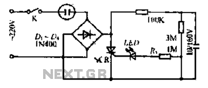
20V child-friendly power supply circuit for a foreign vine wine light, including a bulb and plug. The circuit features a bridge rectifier. The lamp access point is designed for a 10-100W bulb with a compact size. The output is...
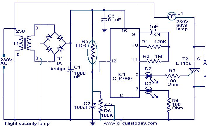
This simple circuit is built around a CMOS IC 4060 to obtain the required timing. During daytime, the LDR has low resistance and keeps pin 12 of IC1 high, preventing IC1 from oscillating. When it is dark, the LDR...