
A Tan TimerCircuit

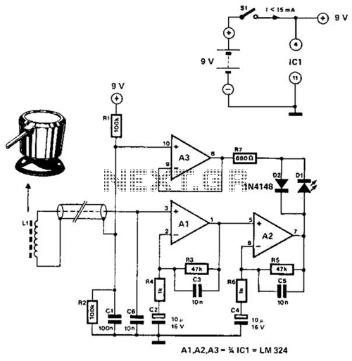
The electronic timer circuit described is intended for use in tanning applications, specifically designed to cater to various skin types by providing six distinct timing positions. Each position corresponds to a recommended exposure duration tailored to the skin's sensitivity to UV radiation. The timer's functionality is influenced by the intensity of sunlight, allowing for dynamic adjustment of exposure times based on real-time environmental conditions.
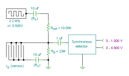
The circuit may utilize a microcontroller or a dedicated timer IC to manage the timing functions. A light sensor, such as a photodiode or phototransistor, can be integrated into the system to measure sunlight intensity. This sensor outputs a voltage signal that varies with the light level, which the microcontroller interprets to adjust the timer settings accordingly.
To implement this functionality, the circuit could include the following components:
1. **Microcontroller**: Acts as the central processing unit to control the timer settings and manage user inputs.
2. **Light Sensor**: Detects the intensity of sunlight and provides feedback to the microcontroller for timing adjustments.
3. **User Interface**: Comprises a set of buttons or a rotary switch allowing users to select the desired timing position based on their skin type.
4. **Display**: An LED or LCD screen to provide visual feedback on the selected timing position and current exposure time.
5. **Relay or Transistor Switch**: Controls the power to the tanning device, enabling or disabling it based on the timer's output.
6. **Power Supply**: Provides the necessary voltage and current for the circuit, which could be powered by batteries or an AC adapter.
The circuit's design should prioritize safety features, such as an automatic shut-off mechanism that activates after the selected exposure time has elapsed, preventing overexposure to UV rays. Additionally, the system could incorporate an alarm or notification system to alert the user when the tanning session is complete.
Overall, this timer circuit is a sophisticated solution that enhances the tanning experience by providing tailored exposure times while considering environmental factors, thereby promoting safe tanning practices.Six timing positions suited to different skin types, Timing affected by sunlight intensity This timer was designed for people wanting to get tanned but at.. 🔗 External reference
Related Circuits
The circuit is capable of enhancing the system power factor to a value exceeding 0.99. It effectively reduces the waveform distortion of the input supply current, ensuring compliance with GB15144 standards, with a distortion index lower than level L....
The schematic consists of three main components. The first component is the sensor circuitry, which connects the accelerometer to the analog-to-digital converters (A/D converters). The second component is the power circuit, featuring an On/Off switch, a 3.7V battery, and...

The circuits utilize two FM Demodulator TDA2555 systems to execute the demodulation functions necessary in a dual sound carrier television system for demodulating the sound carriers. The distinction between the TDA2555 and TDA2557 lies in the number of stages...
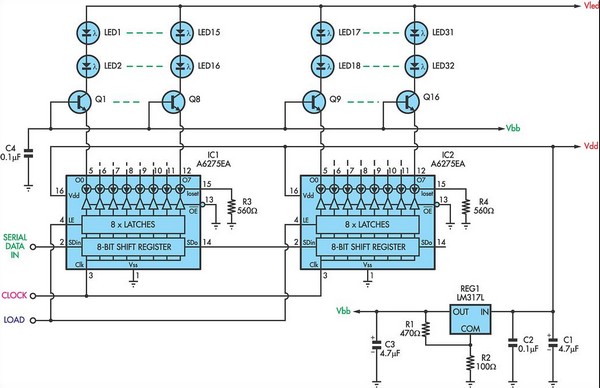
For applications requiring a large number of LEDs, traditional methods can become inefficient, prompting the need to minimize the voltage drop across the resistor. This approach can lead to inadequate current control. Integrated circuits (ICs) like the MM5450 and...
A small transmitter board interfaces with a microcontroller and conductivity probe to measure liquid conductance and conductivity. Precise equations and measurements are provided for this microcontroller-controlled conductivity meter. The described circuit consists of a compact transmitter board that serves as...
The circuit utilizes the principle that in an RL circuit, the pulse width across the inductor is proportional to the inductance. This circuit indirectly measures the inductance using a digital voltmeter (DVM). The measurement range is approximately 5 to...