
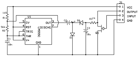
60kv ignition coil driver circuit

The ignition coil driver circuit operates by utilizing the principles of inductive energy storage and discharge. The two ignition coils serve as inductive components that generate a high-voltage pulse when driven by the circuit. The 100µF capacitor is charged through the rectifier, which converts the AC input voltage into a DC voltage suitable for charging the capacitor. The full-wave bridge rectifier ensures that the capacitor receives a consistent voltage, allowing for effective energy storage.
The power resistor or aquarium heater plays a crucial role in managing the discharge of the capacitor. By limiting the current, it prevents damage to the circuit components during the discharge cycle. If a lightbulb is used instead, it not only limits the current but also provides a visual cue indicating the charge status of the capacitor. This feature is particularly useful for users who may not have access to more specialized components.
The optional SCRs can enhance the circuit's functionality by allowing for more controlled discharging of the capacitor. When triggered, the SCRs can facilitate rapid energy release from the capacitor into the ignition coils, generating a high-voltage pulse suitable for applications such as igniting fuel in combustion engines or other high-voltage ignition tasks. The inclusion of a square wave pulse generator adds versatility, enabling the user to adjust the frequency of the pulses, which can influence the performance characteristics of the ignition system.
In summary, this ignition coil driver circuit is a robust design capable of operating at different voltage levels with various components. Its flexibility in component selection and the potential for modifications make it an interesting project for electronics enthusiasts and professionals alike. Proper attention to component ratings and circuit configurations will ensure safe and effective operation.Here is probably the best ignition coil driver circuit that I have seen. As far as I know it was designed by Jochen Kronjaeger. You can find the original at Jochen`s High Voltage Page This circuit is designed to run from 230V, but I have came up with a circuit that will run from 120V about just as well. You will need to find two ignition coils (pr eferably of the same type), a 100uF with at least a 200VDC rating, a full-wave bridge rectifer with a rating of about 5A at 200VDC. A large power resistor with at about 150-200ohms resistance and a power capability of at least 100W, or you can use an aquarium immersion heater.
The next two things are optional, but they will make the project a lot more interesting. You might want to get about three 6A 200VDC SCRs. You can get these from Radio Shack. You might also want a simple square wave pulse generator. This can be just a simple 555 timer circuit. Make sure you can vary the frequency on it. This circuit is fairly easy to build. If you can`t get an SCR, you may also use a TRIAC as a substitute. If you can`t get either then you can use a relay, switch, or just two pieces of wire to trigger it. The contacts will probably be burned out soon though. The resistor or heater is used so that the power doesn`t need to be cut when you discharge the capacitor. It limits the current to a safe value when discharging the capacitor. If you choose not to use the current limiter, the power will have to be unplugged every time you discharge the capacitor.
If you cannot find a heater or power resistor you can also use a common household lightbulb. This will also give you a visual indication when the capacitor is charged. The bulb will go out when the capacitor is fully charged. 🔗 External reference
Related Circuits
Our programmable MP3 player has an interface to an LCD with a HD44780 controller. These are alphanumeric LCDs with one to 4 lines of text and 16 to 40 characters per line. However, these LCDs (and LCDs in general)...
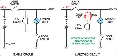
Two headlight reminder circuits are designed for easy installation and operation based on the KISS (Keep It Simple Stupid) principle. The basic circuit consists of a 12V piezo buzzer connected between the lights circuit and a door switch. The...
This circuit is designed to indicate the power output level of any audio amplifier. It is simple, portable, and displays three power levels that can be set to any desired value. The circuit operates by utilizing a combination of resistive...
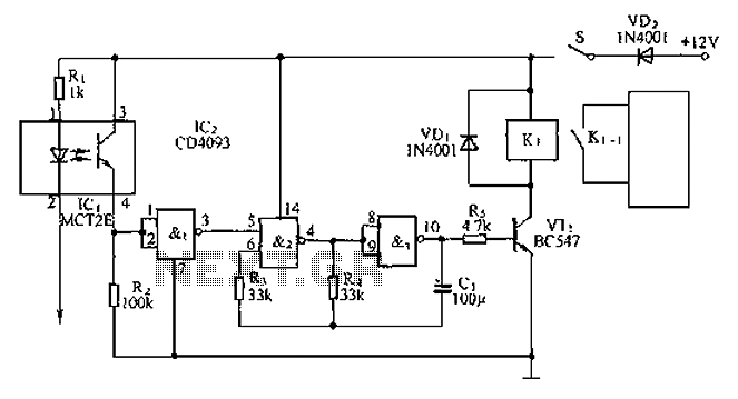
An anti-theft car audio system circuit is depicted, powered by a 12V DC supply from the car battery. Upon closing switch S1, the light-emitting diode in optocoupler IC1 activates, causing the phototransistor to conduct. This results in a high-level...
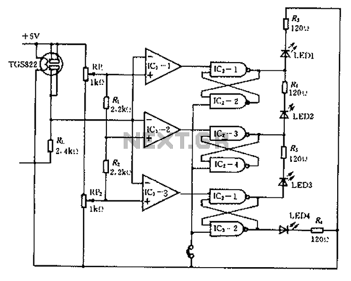
Ceramic gas sensors can be utilized to analyze the content of alcohol vapor. With the appropriate sensor circuit, it is possible to detect blood alcohol content. The operating principle is straightforward: if blood alcohol content is present in a...
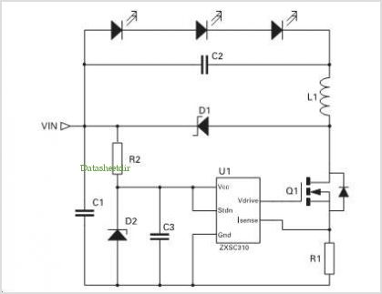
Application of the High Power LED Driver SP7652 with an Analog 0V-to-10V dimmer. Electrical Requirements: Input Voltage of 5.5V to 28V, Output Voltage VF of LED, Output Current ranging from 0 to 6A. This circuit is designed to provide...