
6-Meter preamplifier provides 20db gain

The circuit described involves several key components that are essential for its operation. The trimmer capacitors C1, C2, and C3 allow for fine-tuning of the circuit's resonant frequency, which is critical in applications such as RF (radio frequency) transmission and reception. Their miniature size enables compact designs, making them suitable for integration into smaller electronic devices.
The main transformer T1 is designed with a primary winding of 11 turns of No. 24 enameled wire on a T37-10 toroid core, providing a well-defined magnetic path and efficient inductance. The inductance value of 0.34 µH indicates that T1 is likely intended for high-frequency applications. The single turn antenna winding is designed to capture RF signals effectively, while the three turns of the source winding (Q1) help in establishing a suitable voltage level for further amplification or processing of the received signals.
Transformer T2, which shares the same construction as T1, plays a crucial role in signal transformation. Its primary winding also consists of 11 turns of No. 24 enameled wire on a T37-10 toroid, ensuring consistent performance characteristics. The tap for Q1 drain, located three turns from the end of the winding at C2, facilitates a specific connection point for circuit feedback or signal processing. The secondary winding of T2, composed of three turns, is designed to provide a stepped-down voltage or to couple signals to subsequent stages in the circuit.
T3 mirrors the design of T2, with the only distinction being its secondary winding, which consists of a single turn. This configuration suggests that T3 may be used for applications requiring a minimal voltage step-down or for specific matching purposes in the circuit.
Overall, the described circuit demonstrates a thoughtful arrangement of components aimed at optimizing performance in RF applications, emphasizing the importance of careful winding configurations and the use of trimmer capacitors for precise tuning.Cl, C2, and C3 are miniature ceramic or plastic trimmers- Tl (main winding) is 0.34 µ,. Use of 11 turns of no. 24 enameled wire on a T37-10 toroid core. The antenna winding has one turn, and Ql the source winding has three turns. T2 primary consists of 11 turns of no. 24 enameled wire on a T37-10 toroid. Tap Ql drain is three turns from C2 the end of the winding. The secondary has three turns. T3 is the same as T2, except its secondary has one turn.
Related Circuits
The circuit described is a single JFET design that provides limited gain. By incorporating a source resistor bypass capacitor, the gain can be significantly enhanced, resembling a single stage of the original tube preamp used in guitar amplifiers. It...
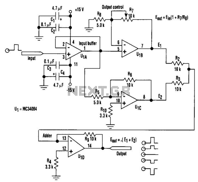
By adjusting one potentiometer, the output of this circuit can be varied from a positive version of the input signal, smoothly transitioning through zero output, and then to a negative version of the input. For instance, if the input...
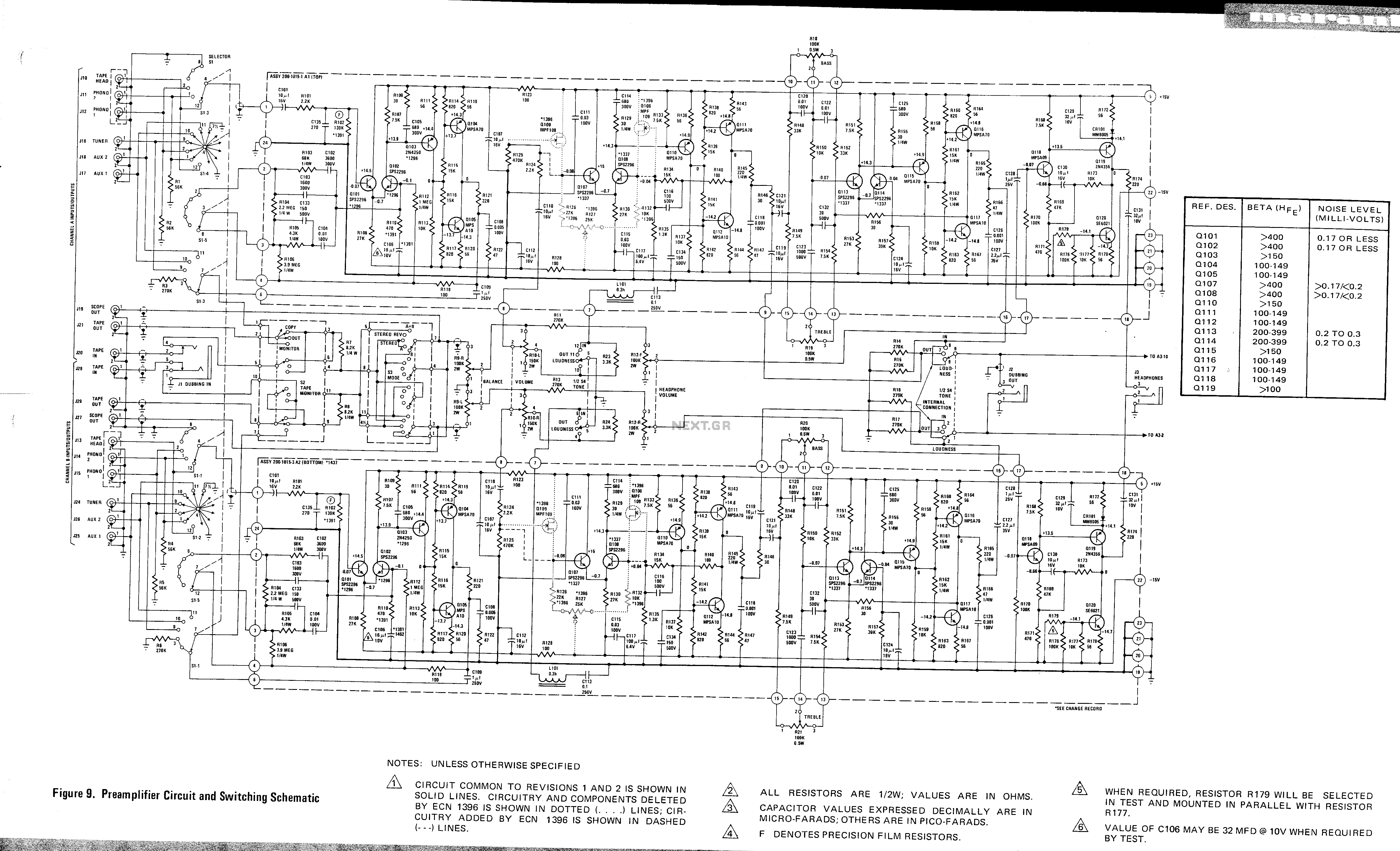
This is a preamplifier circuit and switching schematic for the Marantz Model 33. The Marantz Model 33 preamplifier circuit is designed to amplify low-level audio signals from various sources before sending them to a power amplifier. The schematic typically includes...
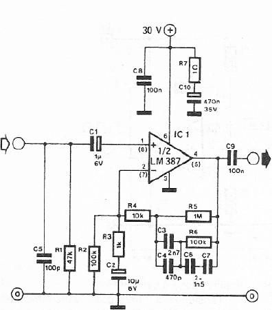
A dynamic microphone preamplifier can be constructed using the LM387 dual operational amplifier integrated circuit. The input impedance is approximately 47k ohms, primarily determined by resistor R1. If a dynamic microphone with a different impedance is to be connected,...
To complement the 60 Watt MOSFET audio amplifier, a high-quality preamplifier design was necessary. A discrete component topology, utilizing +24V and -24V supply rails, was selected, minimizing the transistor count while ensuring low noise, very low distortion, and a...
This circuit is designed to work at UHF frequencies in the range 450-800MHz. It has a gain of around 10dB and is suitable for boosting weak TV signals. The circuit is shown below. The described circuit operates within the Ultra...