
60W power amplifier


POWER SUPPLY
The maximum supply voltage of the IC is +/-40V. However, the maximum dissipation of the IC would be exceeded when using a 4-ohm load at that voltage. Therefore, the supply voltage used should be kept down to a safe +/-30V. The mains transformer used to power the module should be rated at a minimum of 80VA. If two modules are to be run in a stereo amplifier, a common power supply can be utilized, in which case the transformer should be rated at 150VA.
Specifications
Input sensitivity: 1.3V (50W into 8Ω)
Input impedance: 10KΩ
Frequency response: 15Hz - 100kHz
Slew rate: 10V/μs
Output power: 50W into 8Ω (0.1% THD), 82W into 4Ω (0.1% THD)
S/N ratio: 105dBa (1W / 8Ω)
THD (40W into 8Ω): 0.002% (1kHz), < 0.04% (20Hz - 20kHz)
Power Supply: +/-30Vdc
Parts List for Power Amplifier
- R1=180Ω
- R2-3-5=10KΩ
- R4=22KΩ
- R6=680Ω
- C1=1.5μF 63V MKT Polyester
- C2=2.7nF 63V MKT Polyester
- C3-4=100nF 100V MKT Polyester
- C5-6=10μF 63V Electrolytic
- C7=22μF 63V Electrolytic
- C8=33μF 25V Electrolytic
- C9-10=1000μF 63V Electrolytic
- IC1=TDA7294 on Heatsink
- J1=2pin connector with 2.54mm step
- J2=3pin connector
- J3=2pin connector
- JP1-2=2pin Jumper with 2.54mm step
Parts List for Power Supply
- TR1=230Vac//2X22Vac 80VA for single Amplifier
- TR1=230Vac//2X22Vac 150VA for dual Amplifier
- BR1=Diode Bridge >15A
- C1=22nF 630V Polyester MKT
- C2-5=22nF 100V Polyester MKT
- C6-7=10,000μF 63V For single Amplifier
- C8-9=10,000μF 63V For dual Amplifier
- C10-11=1μF 63V Polyester MKT
- F1=Fuse 0.5A slow
This circuit is designed to provide efficient audio amplification while ensuring thermal protection and signal integrity. Proper assembly and adherence to the specifications are critical for optimal performance and reliability.?? ??????? ????? ??? ???????? ?????? ????????? ??? ???????????? TDA7294 ??????????? ??????????, ?? ???? ???? ?????????????? ??? ???. ?? ?????????? ?????? ?????????? ?? ???? ??, ???????????? ?? ????? ????? ???? ?? ?????? 8? ??? 4?. ?? ???? ???? ????????? ????? ??? ??? ???? ??????????? ?????? ?? ????? 50W rms ??? 8? ??? ?????? ????? ??????????? 0.1%. ?????????? ????? ?? ???????????? ?? ??????? ????? ?? ??? ???? ?????? ???????? ?????????? 1,4° C/W ?????????????? ??? ????????? ???????? ????? ????. ???? ????? ?????????? ????? ? ???????? ?????????? ??????????? ??? ??????? ??? ????? ??? ?????????????. ??? ??? ???????????? ???????? ???? ??? ??????? ???? ????? ?? ??? ??????? ?????? ?????? ??? ???????. ?? ???????????? ??????? ????????? ??? ???????????? ???? ????? ?????? ????? ????? 145-150°C, ?????? ????? ??????????? ?? ??? ????????, ??? ?????? Mute ??? Standby ?? ?????? ?? ??? ??????????? ??? ??? ???????????????? JP1-2, ?????????? ???? ?????? ?????? ???????????. ? ?????????? ????? ??? ??????????? ??? ??? ???????? [R3-C6 ??? R4-C5] ??????????? ?????? ???? ?? ?????????? ???????? ??????? ??? ???????? ???? ?? ??????? ??? ???????? ??? ??? ?????? ??? ???????????. ???? ??? ?????? ?? ???????????? ??? ???????? ????? ?? ????? ????????????? ?? ??????. ?????????? ??????? ?? ??? ???????????? ? ???? ??????????? ??? ????????? ???? ?????? ?? ?????? ????? ??? +/-40V. ???? ???? ????? ?? ???????????? ??? ???? ??????????? ??? ??????? +/-30V ?????????????? ???? ????????? ??? ??????? ??????????????, ????? ?????? ??? ????????????? ??????? ??????. ? ?????? ?????? ??? ??? ?????????????? ??????????? ??? ??? ?????? ????? ??????? 80VA ??? ??? ??? ??????? 150VA. ?????????????? ??? ????????? ??? ??????? ???????? ???????? ?? ????? ?? ??? ?????? ?????? ??????????? ?????? ?? ?????????? ????? ??????? 30 ??? 60mA ? ????? ???????? ????????????? ??????????? ??? 10000?F ???????? ?????????? ??? ??? ????? ?????????? ??? ??? ???? ??? ??? ????????. The TDA7294 amplifier module is a monolithic integrated circuit. It is intended for use as an audio class AB amplifier in hi-fi applications. It has a wide voltage range and output current capability, enabling it to supply the highest power into both 4 ohm and 8n ohm loads. With the addition of a handful of parts and a suitable power supply, this module will deliver 50W RMS into 8-ohm with 0.1% THD.
you the user must supply a heavy duty heatsink rated at 1.4°C/W. Pin 10 is the MUTE input and pin 9 provides a STANDBY mode. Muting should always take place before standby mode is selected. Connecting these pins permanently to the supply rail (insert links) ensures that the amplifier comes on immediately on power up. Increasing the time constants R3-C6 and R4-C5 may eliminate any switch-on clicks. The IC has internal thermal protection that causes the mute to cut in at 145°C and switches the amplifier into standby at 150°C.
Do not operate the module without a heatsink. The heatsink tab on the TDA7294 IC is internally connected to the negative supply rail. If the module is mounted inside an earthed metal enclosure then the IC must be insulated from the heatsink. If not, the negative supply rail will be shorted to ground. POWER SUPPLY The maximum supply voltage of the IC is +/-40V. However the maximum dissipation of the IC would be exceeded when using a 4-ohm load at that voltage. Therefore the supply voltage used should be kept down to a safe +/-30V. The mains transformer used to power the module should be rated at a minimum of 80VA. If you want to run two modules in a stereo amplifier you can use a common power supply. In this case the transformer should be rated at 150VA. Source: Quasar Elec. Specifications Input sensitivity 1.3V (50W into 8W) Input impedance 10K Frequency response 15Hz - 100kHz Slew rate 10V/uS Output power 50W into 8W (0.1% THD) 82W into 4W (0.1% THD) S/N ratio 105dBa (1W / 8W) THD (40W into 8W) 0.002% (1kHz) < 0.04% (20Hz - 20kHz) Power Supply +/-30Vdc Parts List for Power Amplifier R1=180ohm C5-6=10uF 63V Electrolytic J2=3pin connector R2-3-5=10Kohm C7=22uF 63V Electrolytic J3=2pin connector R4=22Kohm C8=33uF 25V Electrolytic R6=680ohm C9-10=1000uF 63V Electrolytic All Resistors is 1/4W 1% C1=1.5uF 63V MKT Polyester IC1=TDA7294 on Heatsink All Electrolytic Capacitors is Axial C2=2.7nF 63V MKT Polyester J1=2pin connector with 2.54mm step C3-4=100nF 100V MKT Polyester JP1-2=2pin Jumper with 2.54mm step Parts List for Power supply TR1=230Vac//2X22Vac 80VA for single Amplifier C1=22nF 630V Polyester MKT C8-9=10.000uF 63V For dual Amplifier* TR1=230Vac//2X22Vac 150VA for dual Amplifier C2....5=22nF 100V Polyester MKT C10-11=1uF 63V Polyester MKT BR1=Diode Bridge >15A C6-7=10.000uF 63V For single Amplifier F1=Fuse 0.5A slow
🔗 External reference
Related Circuits

Dual power for each load refers to the operation of two power supplies working simultaneously to handle the electrical load. In the event of a power outage, a contact switch automatically closes all load circuits that are not powered...
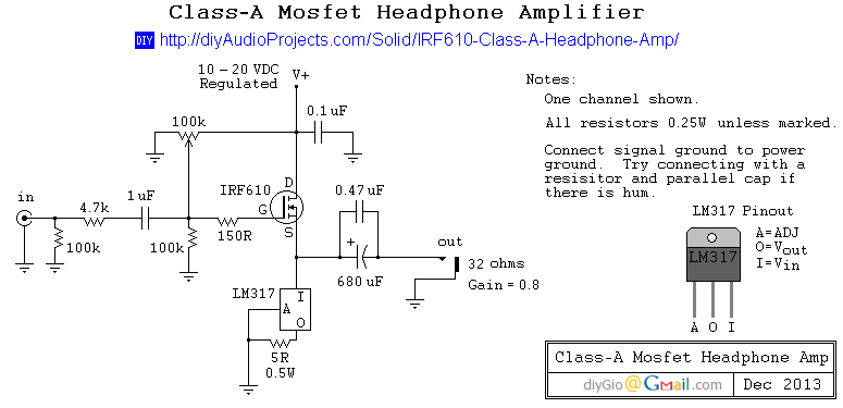
This is a simple and low-cost desktop headphone amplifier designed for office use. The amplifier concept is straightforward and adheres to a typical single-ended Class A circuit. The desktop headphone amplifier utilizes a single-ended Class A design, which is known...
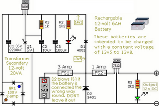
The following circuit illustrates an Alarm Power Supply Circuit Diagram. Features include a 1-amp current output, suitable for a Modular Burglar Alarm operating at 12 volts. The Alarm Power Supply Circuit is designed to provide a stable and reliable power...
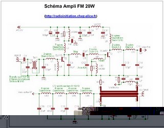
The following circuit illustrates an RF amplifier designed for FM frequencies ranging from 88 to 108 MHz with a broadband configuration. This circuit utilizes the BLV10 transistor. The RF amplifier circuit operates within the FM broadcast band, which is crucial...
This circuit is designed to produce square waves by converting a sine wave obtained from an existing generator. A key feature is that it requires no external power source, allowing for simple connection between a sine wave generator and...
For circuits using TTL ICs, the supply voltage is a significant concern, as even a slight increase from the rated 5V can damage the IC. Relying solely on fuses is insufficient since a fuse may take several milliseconds to...