
Dual power supply circuit contactor mutual investment 2

The dual power supply system is designed to enhance reliability and ensure uninterrupted power delivery to critical loads. This system typically employs two independent power sources, which can be either from different locations or different types of supplies (e.g., mains and generator). The automatic transfer switch (ATS) or contact switch plays a crucial role in this setup, as it detects when one power source fails and seamlessly transitions the load to the alternative source without manual intervention.
In normal operation, the load is divided between the two power supplies. For instance, load segment A receives power from bus No. 1, while load segment B is connected to bus No. 2. This configuration not only balances the load but also provides redundancy. If one power source fails, the ATS quickly disconnects the failed source and connects the load to the functioning power supply, ensuring continuous operation.
The importance of circuit breakers QFi and QF2 cannot be overstated. These breakers are equipped with auxiliary contacts that ensure they operate in a synchronized manner. The mechanical interlock feature is critical; it prevents both breakers from closing at the same time, which could result in a short circuit due to the merging of two different power sources. The design must adhere to safety standards to mitigate risks associated with electrical faults, including overloads and short circuits.
The schematic diagram for this dual power supply system typically includes the two power sources, the ATS, circuit breakers, and the load segments. Each component must be rated appropriately to handle the expected load and fault conditions. Additionally, proper labeling and a clear layout are essential for maintenance and troubleshooting purposes.
Overall, a dual power supply system is an effective solution for applications requiring high availability and reliability, such as in data centers, hospitals, and critical industrial processes. Proper design, implementation, and maintenance of such systems are vital to ensure they perform as intended, providing peace of mind and operational continuity.Dual power for each load refers to work simultaneously by the two-way power supply and two power supplies, respectively, the burden of electricity load. When at the way in whic h the power outage, contact switch automatically closing all the load circuit is not powered by power outages. Circuit is shown. Under normal circumstances, the power to 1 A load segment power bus No. 2 to the power supply section B bus load. Note: The circuit breaker QFi, QF2 auxiliary contacts must At a time (available mechanical tone than the main contacts first action the whole), otherwise two different power sources will merge in an instant, causing a short circuit.
Related Circuits
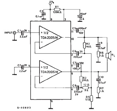
TDA2005 car audio amplifier circuit diagram electronic project using few external electronic parts The TDA2005 is a robust integrated circuit designed for audio amplification in automotive applications. This circuit diagram outlines a project for a car audio amplifier that utilizes...
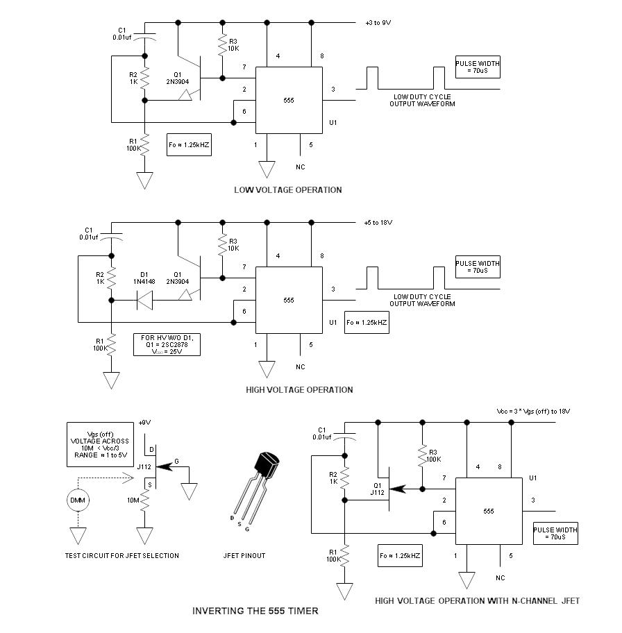
When using the 555 timer, the output polarity often appears to be incorrect, as the 555 typically cannot produce a duty cycle of less than 50%. This inverted 555 circuit is capable of generating duty cycles below 50%. The...

A simple transistor amplifier circuit diagram and schematic that can be used as a 12-watt audio transistor amplifier. An operational amplifier (op-amp) integrated circuit (IC) is used to produce the required gain. This circuit is designed to amplify audio signals,...
This appears to be an infrared (IR) transmitter. IR signals do not penetrate walls, and it is assumed that this device is intended for use in a room separate from the one in which the user is located, rendering...
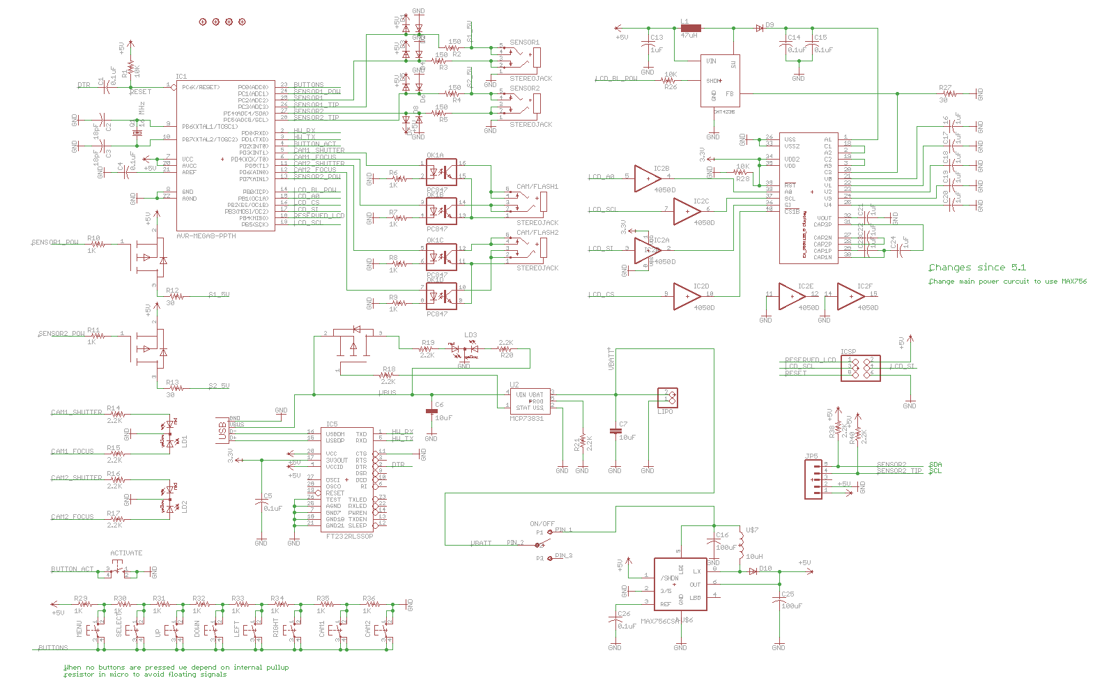
Previously, a linear regulator was used, but a Max756 boost converter is now in operation. An output ripple of 0.1 to 0.3V is observed in the current, while the Max756 datasheet indicates an expected ripple of about 50 mA....
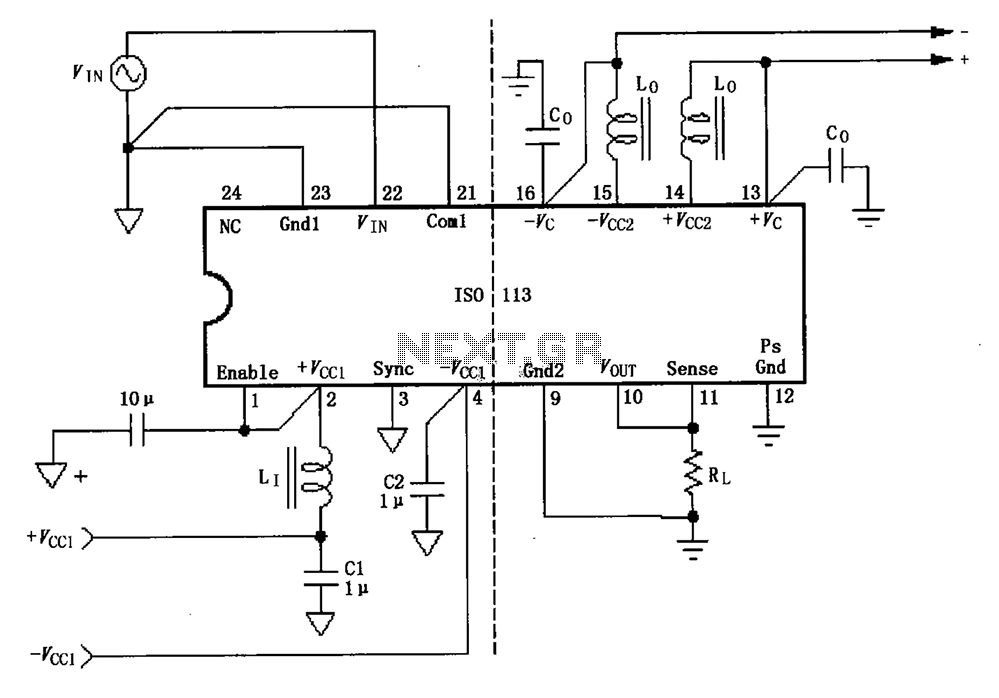
The basic connection circuit for the ISO113 signal and power supply is illustrated. Each power supply terminal must include a bypass filter. If the output current from the isolated power supply exceeds 15mA, it is advisable to utilize an...