
60W Power Amplifier with 2N3055

The described circuit is a simple audio amplifier designed to deliver approximately 60 watts of output power, suitable for driving speakers in various audio applications. The amplifier operates optimally at a supply voltage of 50V, but it is versatile enough to function within a range of 30V to 60V. This flexibility allows for the use of readily available components, which can be sourced from common electronic parts.
The input stage of the amplifier accepts a maximum input voltage of around 0.8V to 1V, making it compatible with standard audio signal levels. The use of NPN power transistors is essential for the output stage, as these components provide the necessary current amplification. It is important to avoid using Darlington pairs in this design due to their higher voltage drop and slower switching times, which could adversely affect performance.
Capacitor C1 plays a critical role in shaping the low-frequency response of the amplifier. By increasing the capacitance of C1, the amplifier can enhance the bass response, allowing for a richer sound at lower frequencies. Conversely, capacitor C2 is responsible for regulating the higher frequencies. Increasing the capacitance of C2 results in a reduction of treble output, which can be useful for tuning the amplifier to suit specific audio preferences or speaker characteristics.
Overall, this design emphasizes simplicity and cost-effectiveness while maintaining sufficient performance for general audio amplification tasks. The tolerance for component selection allows hobbyists and engineers to utilize a wide variety of parts, making it an accessible project for those looking to build their own audio amplifier.Simple and low cost. The optimal supply voltage is around 50V, but this amp work from 30 to 60V. The maximal input voltage is around 0.8 - 1V. As you can see, in this design the components have a big tolerance, so you can build it almost of the components, which you find at home. The and transistors can be any NPN type power transistor, but do not use Darlington types... The output power is around 60W. - capacitor C1 regulates the low frequencies (bass), as the capacitance grows, the low frequncies are getting louder. - capacitor C2 regulates the higher frequencies (treble), as the capacitance grows, the higher frequencies are getting quiter.
- this i 🔗 External reference
Related Circuits
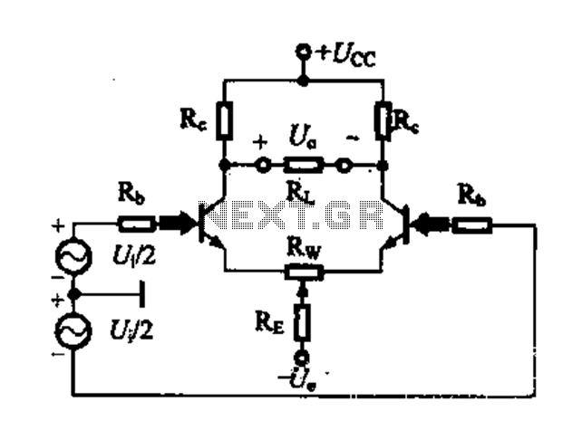
A differential amplifier circuit can be configured in four different connection methods, allowing for a comparison of characteristics such as gain and common-mode rejection ratio (CMRR). This analysis focuses on symmetrical circuits and their performance in handling common-mode signals. The...
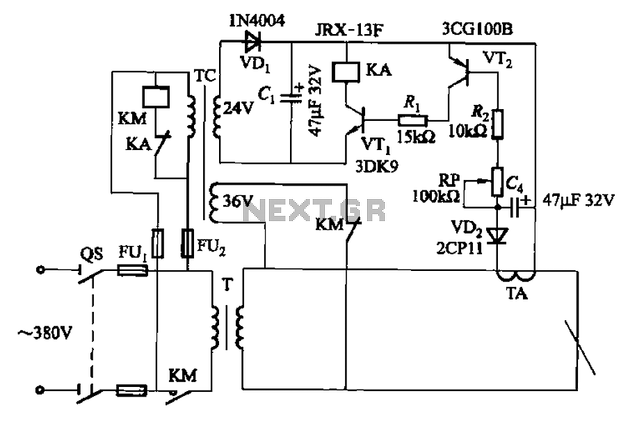
The AC arc welding machine's transistor load path for the power from the second circuit is illustrated. The figure shows a current transformer with a core cross-section of 25 mm². The transformer has a primary winding with a certain...
This solid-state push-pull single-ended Class A circuit is capable of providing sound quality comparable to valve amplifiers, delivering an output power of 6.9W measured across an 8 Ohm loudspeaker cabinet load. It exhibits lower total harmonic distortion (THD), higher...
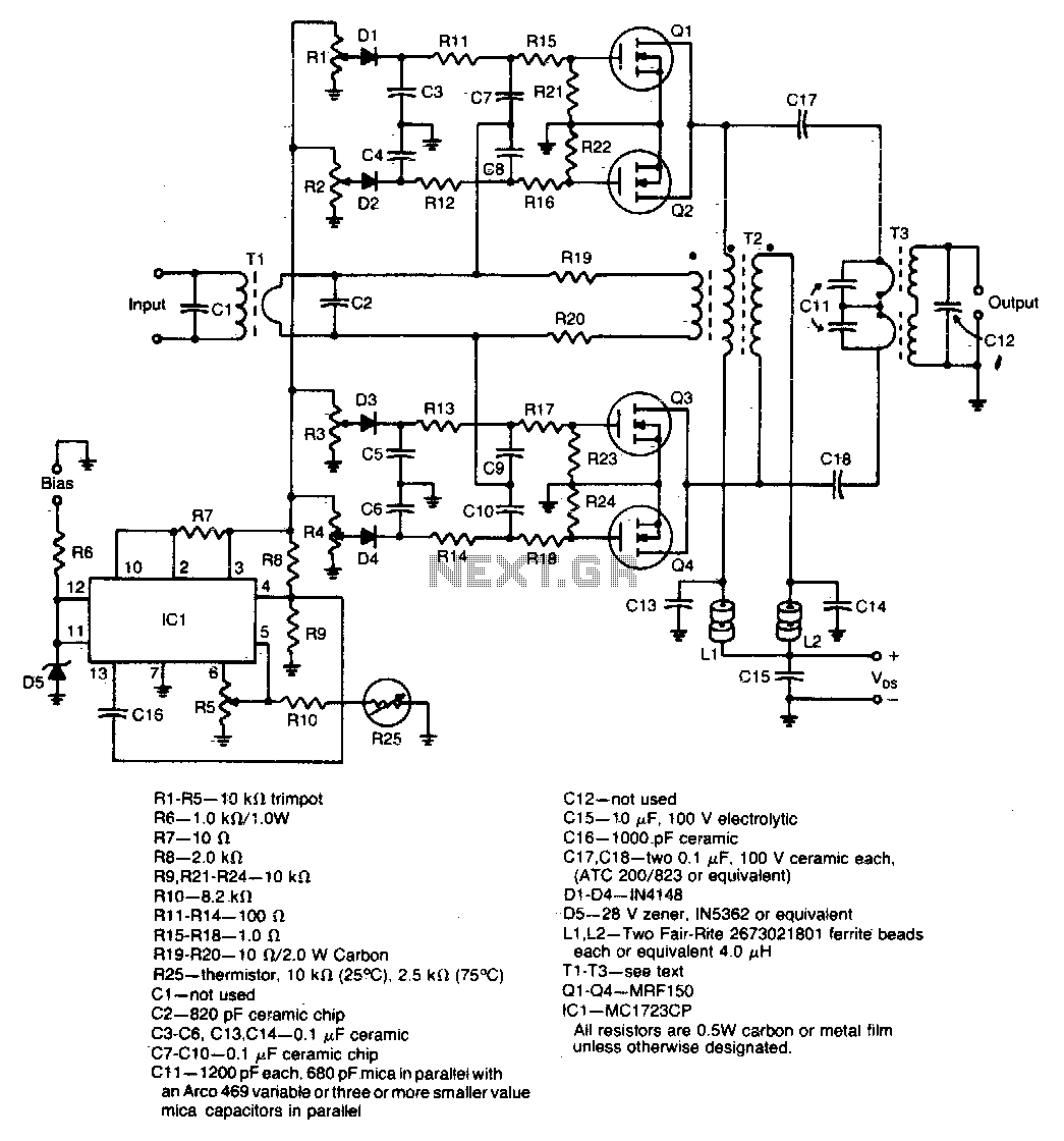
A unique push-pull parallel circuit utilizes four MRF150 RF power FETs connected in parallel at relatively high power levels. Supply voltages ranging from 40 to 50 Vdc can be employed, contingent on the linearity requirements. The bias for each...
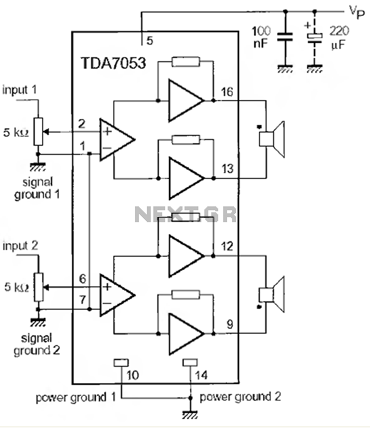
This is a 1-watt stereo audio amplifier circuit utilizing the TDA 7053 integrated circuit from Philips. It is specifically designed for battery operation, delivering 1 watt per channel from a 6V DC supply. The circuit operates optimally between 6V...

These circuits are useful for video applications up to 10 MHz. The 3.3-pF capacitors serve as compensation capacitors. The capacitors connected to pins 7 and 4 act as bypass capacitors to prevent self-oscillations. Figure 76-18(a) illustrates a non-inverting configuration,...