
5 Watt Class-A Audio Amplifier Circuit

This Class A amplifier circuit utilizes a push-pull configuration to enhance audio fidelity while minimizing distortion. Solid-state components, specifically transistors, are employed to achieve the desired performance. The output stage consists of two transistors (Q2 and Q3) operating in a complementary manner, allowing for efficient amplification of both halves of the audio waveform. The chosen output power of 6.9W is suitable for driving an 8 Ohm loudspeaker, making it ideal for home audio applications.
The power supply requirements of 24V and 700mA are relatively modest compared to traditional valve amplifiers that often require high-voltage supplies. This lower voltage operation contributes to the overall efficiency of the circuit, reducing the risk of overheating and improving reliability. Despite the lower voltage, careful design ensures that the amplifier can deliver high-quality sound with minimal distortion.
Thermal management is a critical aspect of this design. The necessity for a large heatsink for the output transistors is due to the power dissipation that occurs during operation. Proper heatsinking is essential to maintain the transistors within their safe operating temperature range, ensuring longevity and stable performance.
The optional bass-boost feature, implemented with R5 and C5, allows users to tailor the audio output to their preferences. This feature can enhance lower frequencies, providing a richer sound experience, particularly for music genres that benefit from increased bass response. The design of the circuit accommodates this modification without compromising the integrity of the overall audio performance.
Overall, this solid-state Class A amplifier circuit combines the warmth and richness typically associated with valve amplifiers while offering the advantages of modern solid-state technology, making it a compelling choice for audio enthusiasts seeking high-quality sound reproduction.This solid-state push-pull single-ended Class A circuit is capable of providing a sound comparable to those valve amplifiers, delivering more output power (6. 9W measured across a 8 Ohm loudspeaker cabinet load), less THD, higher input sensitivity and better linearity.
Voltage and current required for this circuit are 24V and 700mA respectively, co mpared to 250V HT rail and 1A @ 6. 3V filament heating for valve-operated amplifiers. The only penalty for the transistor operated circuit is the necessity of using a rather large Heatsink for Q2 and Q3 (compared to the maximum power delivered). In any case, the amount of heat generated by this circuit can be comparable to that of a one-valve amplifier.
An optional bass-boost facility can be added, by means of R5 and C5. 🔗 External reference
Related Circuits
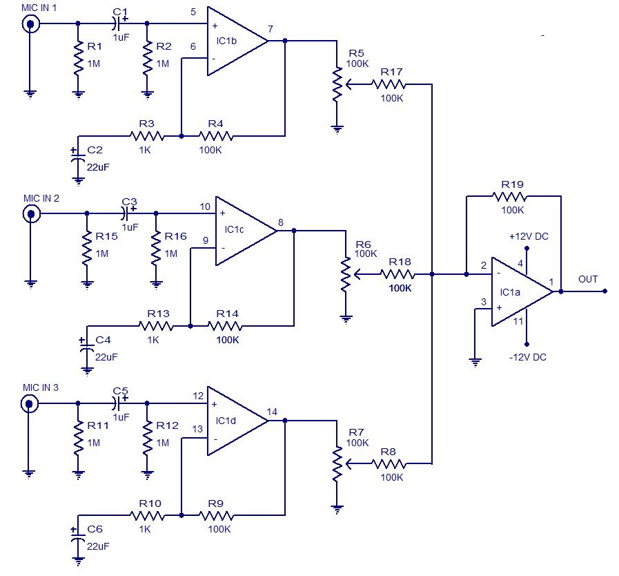
The circuit presented is a three-input microphone mixer and preamplifier utilizing the LM348 integrated circuit. The LM348 is a high-gain, internally compensated quad operational amplifier featuring a class AB output stage. It has a very low input supply current...
This time, we will share information about Yo3dac's homebrew RF circuit design ideas, including the latest updates from Onmilwiki. Yo3dac is known for innovative approaches in the realm of radio frequency (RF) circuit design, particularly within the homebrew community. The...

This circuit features a high-input-impedance AC resistance of 880 kΩ and a gain of 10, utilizing an operational amplifier for a piezoelectric transducer. The described circuit is designed to interface with a piezoelectric transducer, which generates an AC voltage in...
This project involves constructing an energy-efficient broad spectrum LED lamp system designed for indoor reflective room lighting. The lamp provides a broad color spectrum that closely resembles natural sunlight compared to fluorescent bulbs and white-only LEDs. The light output...
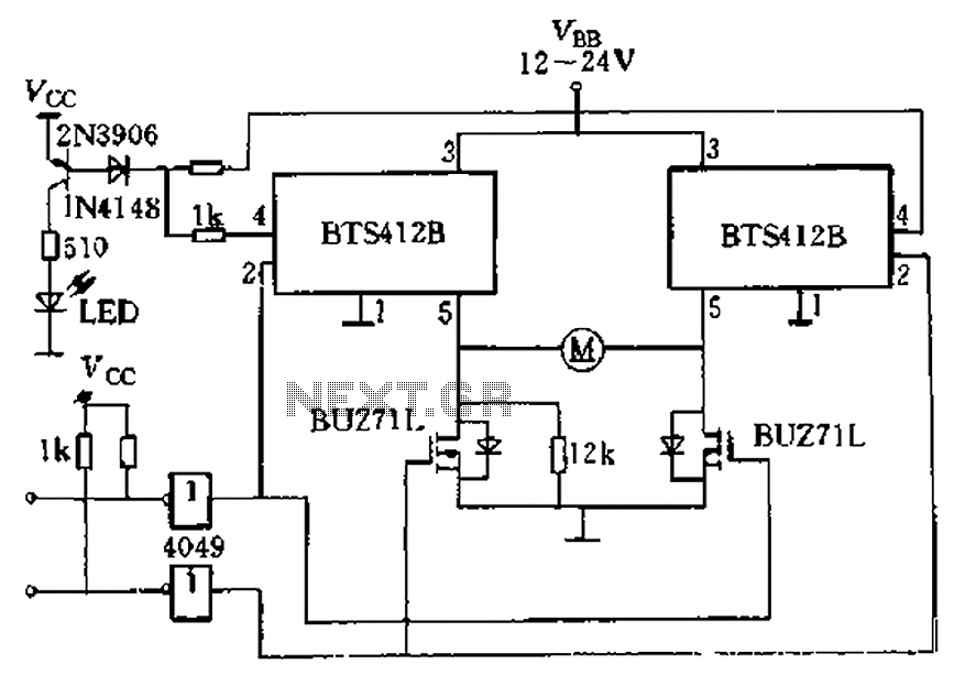
The BTS412B functions as two high-side power MOSFET switches, while two BU271L (50V, Zhang 1n) serve as low-side switches, forming a bi-directional H-bridge DC motor drive circuit. This configuration is designed for electrical automatic door systems, capable of handling...
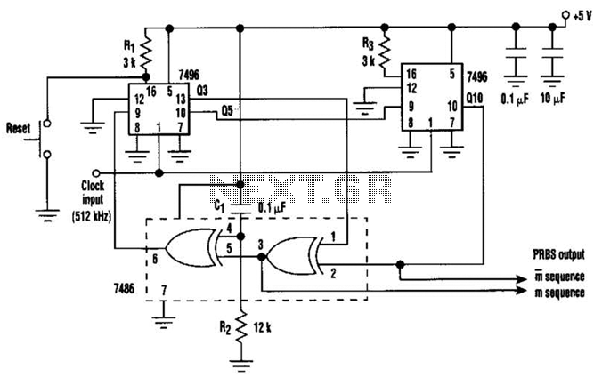
In this circuit, an additional exclusive-OR gate is connected after the modulo-2 feedback, with CI and R2 applying the supply turn-on ramp into the feedback loop. This provides sufficient transient signal so that the PRBS generator can self-start during...