
69 SFPR Schematic Telecaster Guitar

The Princeton Reverb amplifier, particularly the model from 1969, is renowned for its warm tone and versatile sound characteristics, making it a favorite among musicians. The AA764 circuit is notable for its design simplicity and effectiveness, providing a rich, clean sound with ample reverb and vibrato effects.
In the AA764 circuit, the preamp section typically consists of two 12AX7 tubes, which amplify the input signal before it reaches the tone control stage. The tone control circuit allows for adjustment of bass and treble frequencies, shaping the amplifier's overall sound profile. Following the tone control, the signal passes to the phase inverter, which prepares the signal for the power stage.
The power section of the AA764 circuit employs a pair of 6V6 power tubes, delivering a warm and dynamic output. The output transformer is designed to match the impedance of the speaker, ensuring optimal power transfer and sound quality. The reverb circuit is integrated into the design, utilizing a spring reverb tank that adds depth and ambiance to the sound.
Additionally, the amplifier features a tremolo circuit, which modulates the amplitude of the signal, creating a pulsating effect that enhances the playing experience. The overall layout of the AA764 circuit is designed for reliability and ease of maintenance, with clearly defined pathways for signal flow and power distribution.
This combination of features makes the 1969 Princeton Reverb with the AA764 circuit an enduring choice for both studio and live performances, offering a blend of classic Fender tone and modern functionality.I have a 69 Princeton Reverb which is labled as having an AA764 circuit. When perusing various web resources for Fender Amplifier Schematics.. 🔗 External reference
Related Circuits
In this doorphone circuit, an 8 ohm speaker is used both as a microphone and also an output device. The BC109C stage amplifies in common base mode, giving good voltage gain, whilst providing a low impedance input to match...
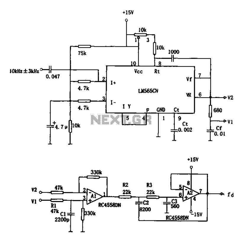
The circuit utilizes a 10 kHz and 3 kHz LM565CN to create an FM demodulation setup. The output diagram (b) illustrates the differential demodulation outputs V1 and V2 from the differential amplifier A1, which provides level displacement and amplification....
This guitar amplifier electronic architecture utilizes a robust conventional circuit design for the power amplifier, employing a single-rail supply of approximately 60V and capacitor coupling for the speakers. The advantages of this configuration for a guitar amplifier include a...
The figures below illustrate using opamps as active 2nd order filters. Three 2nd order filters are shown, low pass, high pass, and bandpass. Each of these filters will attenuate frequencies outside their passband at a rate of 12dB per...
This circuit uses the effect of a FET as the power to act through the gate with the source to connect. The voltage may vary between 4V and 30V, the current through the LED should constantly be around 15mA....
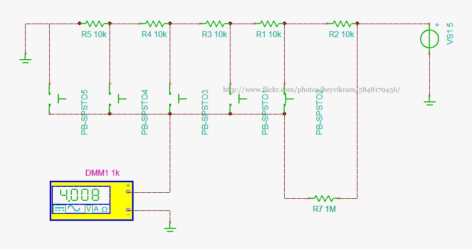
Connect a 5-way button/joystick to an Arduino using a single analog pin to quickly simulate it for verification of calculations before soldering. The voltages for the six states are 0, 1, 2, 3, 4, and 5. The 4V displayed...